Electrical connection box and wire harness

Active Publication Date: 2017-03-02
YAZAKI CORP
View PDF33 Cites 9 Cited by
  • Summary
  • Abstract
  • Description
  • Claims
  • Application Information

AI Technical Summary

Benefits of technology

[0007]An object of the present invention is to provide an electrical connection box and a wire harness which allow compatibility between inhibitin

Problems solved by technology

However, when the power supply connection portion is merely covered, heat generated in the power supply c

Method used


Image

  • Electrical connection box and wire harness
  • Electrical connection box and wire harness
  • Electrical connection box and wire harness

Examples


embodiment

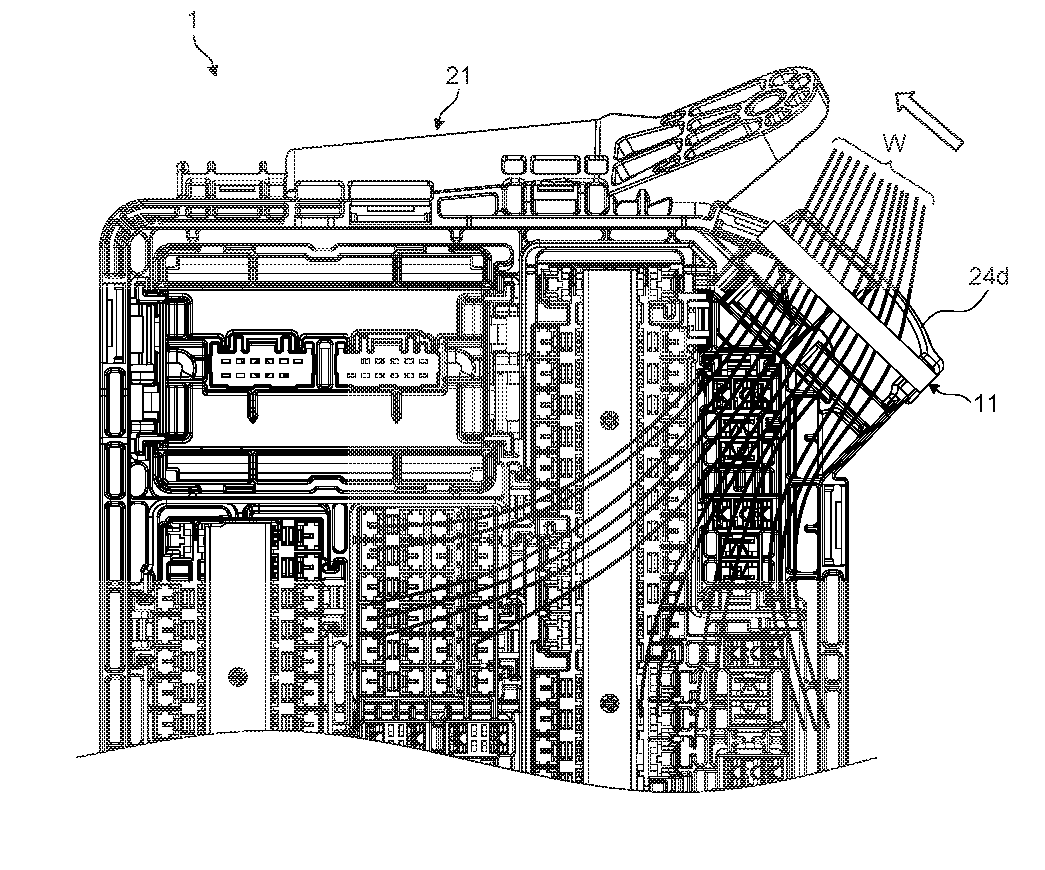
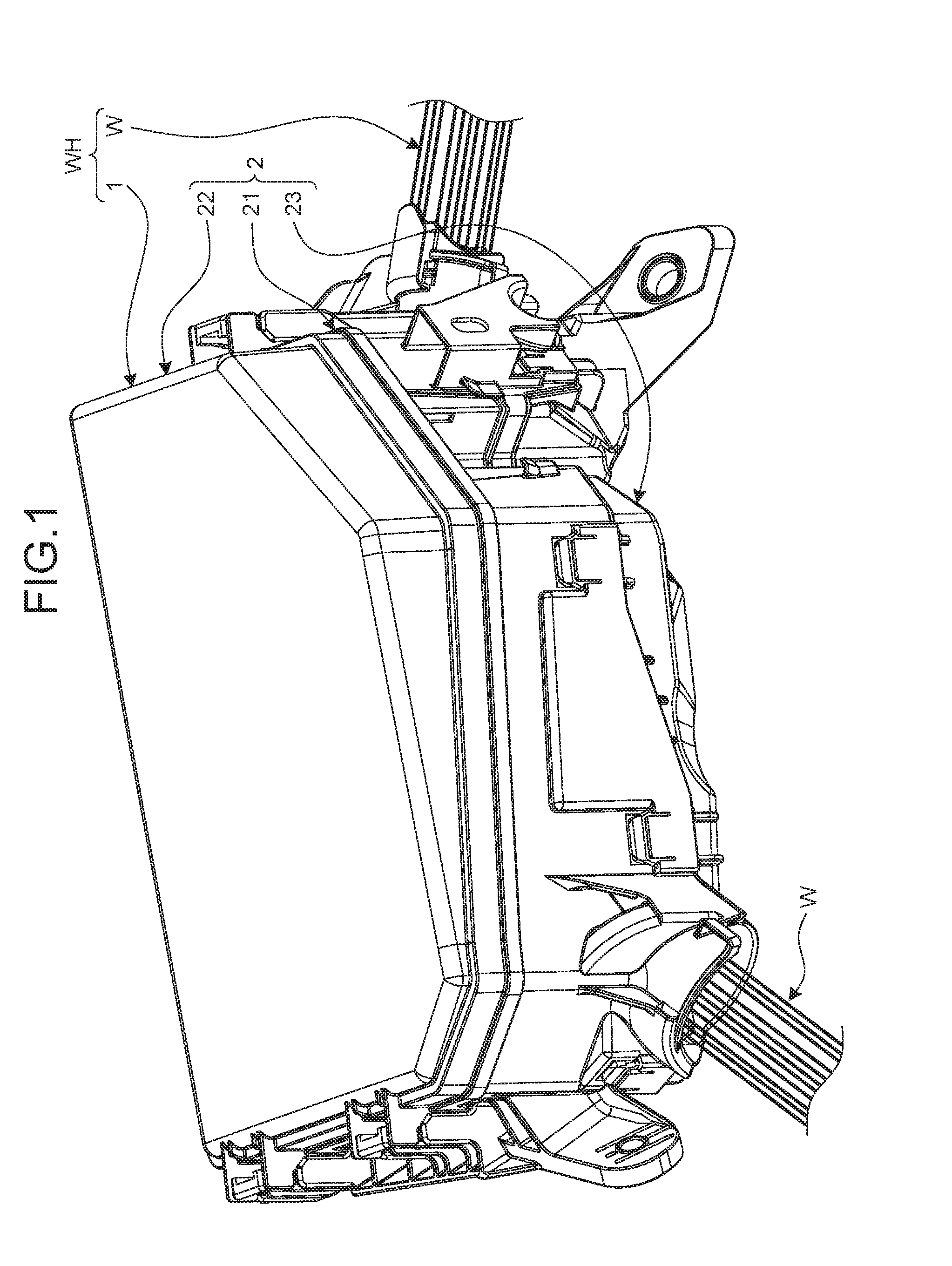
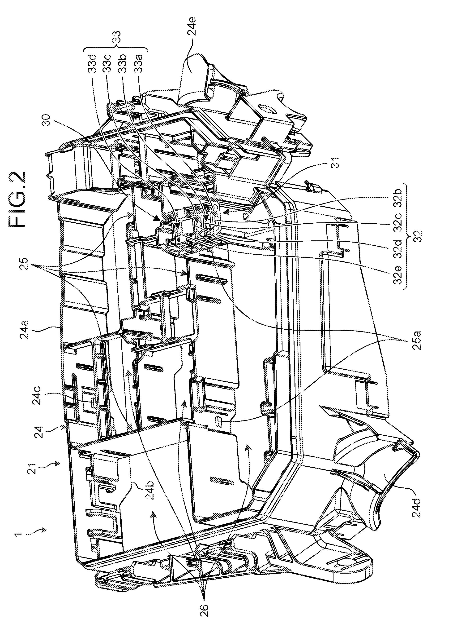
[0025]An embodiment will be described with reference to FIG. 1 to FIG. 11. The present embodiment relates to an electrical connection box and a wire harness. FIG. 1 is a perspective view of the electrical connection box and the wire harness according to the embodiment of the present invention, FIG. 2 is a perspective view of a frame according to the embodiment, FIG. 3 is a perspective view of a lower cover according to the embodiment, FIG. 4 is a perspective view illustrating an inside of the electrical connection box according to the embodiment, FIG. 5 is a perspective view illustrating a power supply connection portion according to the embodiment, FIG. 6 is a perspective view illustrating the power supply connection portion and a holding member according to the embodiment, FIG. 7 is a plan view illustrating the inside of the electrical connection box according to the embodiment, FIG. 8 is a cross-sectional view related to the power supply connection portion and a cover portion acc...

modified example of embodiment

[0045]A modified example of the embodiment will be described. In the above embodiment, the cover portion 30 is formed integrally with the frame 21. However, the cover portion 30 and the frame 21 may be different bodies. In this case, the cover portion 30 may be attached to and detached from the frame 21, and may be attached to and detached from the holding member 9. The cover portion 30 preferably has higher thermal conductivity than thermal conductivity of the frame 21. The cover portion 30 may have a heat radiating fin. The ribs 37 may serve as the heat radiating fin.

[0046]An aspect of connection between the external power supply and the power supply connection portion 5 is not restricted to an example in the above embodiment. For example, a fixing means for fixing the terminal 10 is not restricted to the screw 7 and the nut 8. For example, the electric wires W connected to the external power supply may be connected to the power supply connection portion 5 without the terminal 10 ...


PUM


Abstract

An electrical connection box includes a case including a frame that holds electronic components and a cover that blocks an opening portion of the frame, a power supply connection portion provided inside the case, an external power supply being connected to the power supply connection portion, and a cover portion that covers the power supply connection portion from above, in which the cover portion has a hole portion that communicates a space portion on a side of the power supply connection portion with respect to the cover portion with a space portion above the cover portion inside the case, and is configured to detachably hold a component.

Description

CROSS-REFERENCE TO RELATED APPLICATION(S)[0001]The present application claims priority to and incorporates by reference the entire contents of Japanese Patent Application No. 2015-171084 filed in Japan on Aug. 31, 2015.BACKGROUND OF THE INVENTION[0002]1. Field of the Invention[0003]The present invention relates to an electrical connection box and a wire harness.[0004]2. Description of the Related Art[0005]There has been an electrical connection box having a power supply connection portion to which an external power supply is connected. For example, Japanese Patent Application Laid-open No. 2013-17295 discloses a technology of an electrical connection box having a fuse block provided with a power supply input terminal electrically connected to a power supply.[0006]When a power supply connection portion is exposed inside an electrical connection box, there is a possibility that a finger or a tool will touch a metal portion. It is effective to cover the power supply connection portion ...

Claims


Application Information

Patent Timeline
IPC IPC(8): H02G15/117H01B7/00
CPCH01B7/0045H02G15/117H02G3/081B60R16/0238
Inventor KAWADA, DAISUKEKOMIYA, YUKIKIYOTA, HIROTAKA
Owner YAZAKI CORP
Why Eureka
Try Eureka