Cooling device for high temperature pipe

Inactive Publication Date: 2019-02-21
MITSUBISHI HEAVY IND LTD
View PDF5 Cites 0 Cited by
  • Summary
  • Abstract
  • Description
  • Claims
  • Application Information

AI Technical Summary

Benefits of technology

[0037]According to the cooling device for a high temperature pipe of the present invention, the cooling medium supply header having the cooling medium outflow nozzle is disposed on the peripheral part of the surface to be cooled, and therefore any member for shielding heat dissipation by radiation from the surface to be cooled to the periphery is not disposed. Thus, heat dissipation is effectively performed from the surface to be cooled, so that it is possible to i

Problems solved by technology

When such metallic pipes are used under the above environment for a long time, creep damage progresses to generate creep voids, and then these creep voids are linked to generate a crack, which is likely to result in fracture.
In this case, the metallic pipes generally have high cre

Method used


Image

  • Cooling device for high temperature pipe
  • Cooling device for high temperature pipe
  • Cooling device for high temperature pipe

Examples


first embodiment

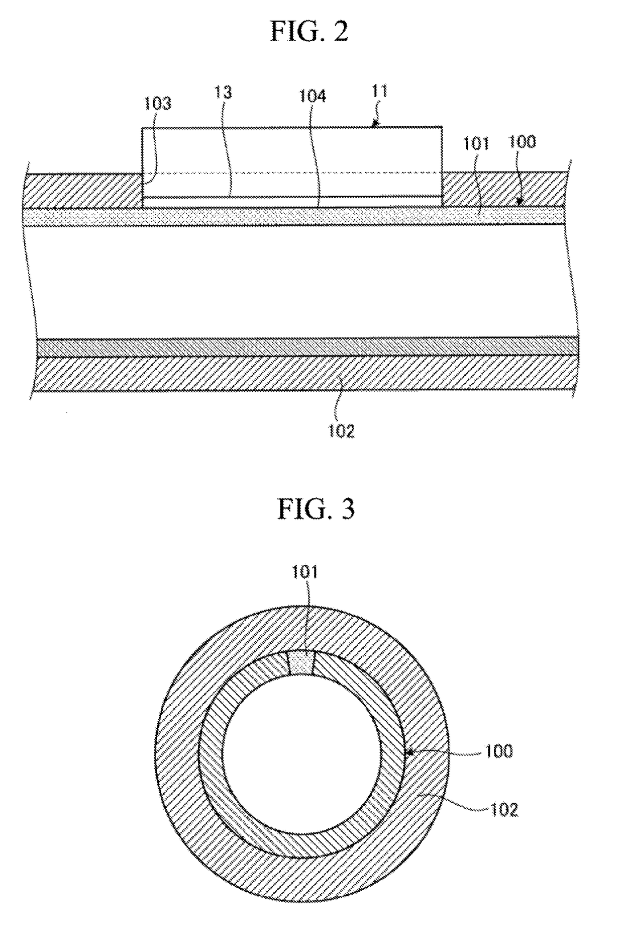
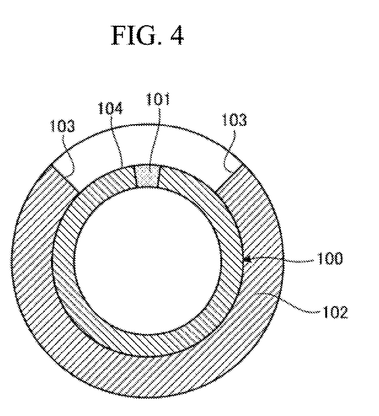
[0060]FIG. 3 is a sectional view illustrating a high temperature pipe, and FIG. 4 is a sectional view of the pipe having a partially removed heat insulating material.

[0061]In the first embodiment, the high temperature pipe is a metallic steam pipe that conveys, to a steam turbine, steam heated by a boiler, in a thermal power plant, for example, and is a high temperature metallic pipe heated by high temperature and high pressure steam that flows therein. Nondestructive inspection for this metallic pipe is performed on a regular basis, the growing degrees of creep voids of the pipe are analyzed to derive the degree of creep damage, and residual life assessment of the pipe is performed. In a case where the creep damage risk in a period until next periodic inspection cannot be ignored, the high temperature metallic pipe is cooled to lower the temperature, so that the creep damage risk is reduced.

[0062]In a cooling device for a high temperature pipe of this embodiment, an exposed surface...

second embodiment

[0125]FIG. 20 is a schematic diagram illustrating a cooling device for a high temperature pipe of a second embodiment, and FIG. 21 is a schematic diagram illustrating a first modification of the cooling device for a high temperature pipe of the second embodiment. Members having similar functions as the members of the above first embodiment are denoted by the same reference numerals, and detailed description is omitted.

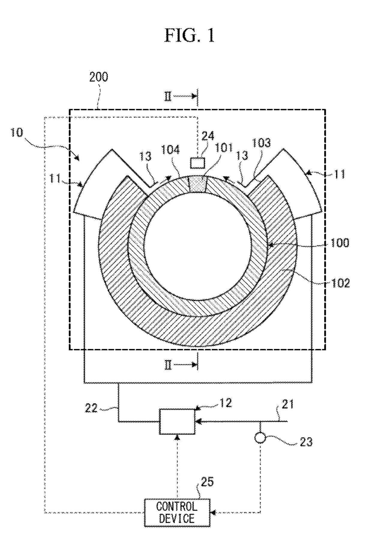
[0126]In the second embodiment, as illustrated in FIG. 20, a cooling device 50 for a high temperature pipe cools a surface to be cooled 104 of a metallic pipe 100, and includes cooling medium supply headers 51, a cooling medium supply device 52, cooling medium outflow nozzles 53, and a hood 200.

[0127]The cooling medium supply headers 51 are disposed so as not to shield heat dissipation by radiation from the surface to be cooled 104 of the pipe 100. The respective cooling medium supply headers 51 are disposed on both sides in the circumferential direction in an uncovere...


PUM


Abstract

In a cooling device for a high temperature pipe, a high temperature pipe is efficiently cooled, and cooling performance is improved. A cooling device (10) for a high temperature pipe that cools a surface to be cooled (104) of a pipe (100) as a high temperature pipe includes: a cooling medium supply header (11) that is disposed so as not to shield heat dissipation by radiation from the surface to be cooled (104) to the periphery, and allows a cooling medium to flow out toward the surface to be cooled (104); and a cooling medium supply device (12) that supplies the cooling medium to the cooling medium supply header (11).

Description

TECHNICAL FIELD[0001]The present invention relates to a cooling device for a high temperature pipe used in a plant such as a thermal power plant, an atomic power plant, and a chemical plant.BACKGROUND ART[0002]For example, in a thermal power plant, a large number of pipes for conveying steam heated by a boiler to a steam turbine are disposed. These pipes are metallic pipes and allow high temperature and high pressure steam to flow therein. Therefore, they are under environment of a high temperature state heated by this steam. When such metallic pipes are used under the above environment for a long time, creep damage progresses to generate creep voids, and then these creep voids are linked to generate a crack, which is likely to result in fracture.[0003]In order to prevent such fracture of the pipes, the growing degrees of the creep voids are analyzed by regular nondestructive inspection to derive the degree of creep damage, and residual life assessment of the metallic pipes is perfo...

Claims


Application Information

Patent Timeline
IPC IPC(8): F16L53/70F01K11/02
CPCF16L2201/20F16L53/70F01K11/02F16L2201/40
Inventor MATSUO, TAKESHISAKATA, FUMITOSHIKANEMAKI, YUICHIMUKUMOTO, HARUKIWATANABE, DAIGOKATO, CHIKAKOOZAWA, JUNICHIJOYAMA, JUNKIKUROSE, MASAHIROFUJIMORI, TAKAHIROOHYAMA, HIROYUKI
Owner MITSUBISHI HEAVY IND LTD
Why Eureka
Try Eureka