

Nuclear Reactor Containment Vessel and Nuclear Reactor
- Summary
- Abstract
- Description
- Claims
- Application Information
AI Technical Summary
Benefits of technology
Problems solved by technology
Method used
Image

Examples
embodiment 1
[0017]In order to facilitate understanding of this embodiment, a comparative example of a nuclear reactor containment vessel cooling equipment of a nuclear power generation plant will be described.
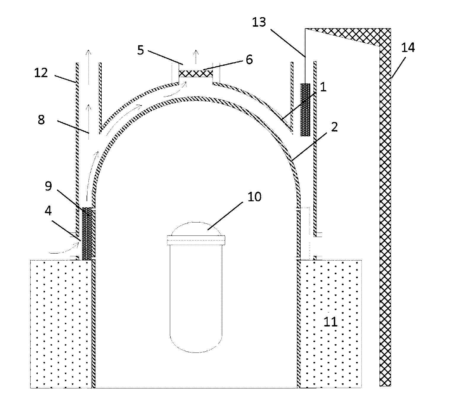
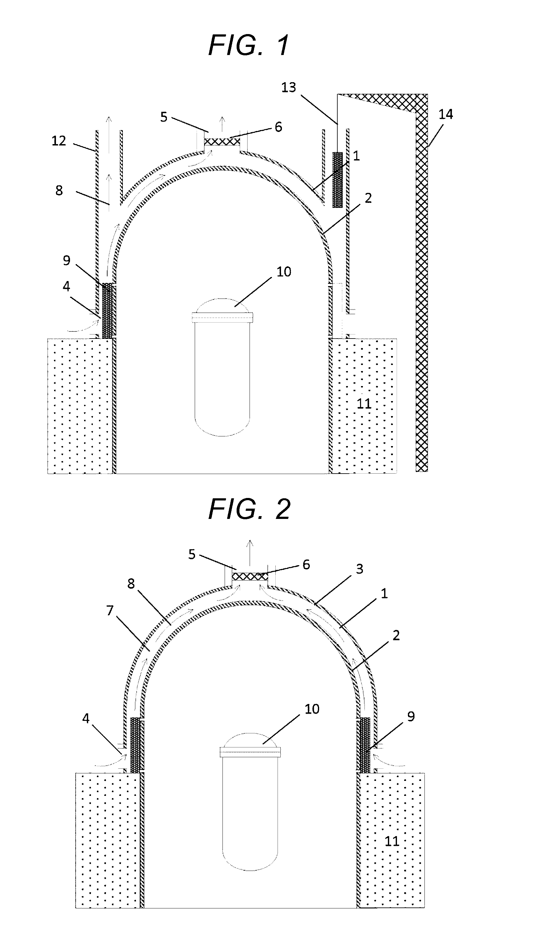
[0018]FIG. 2 is a structural view of the nuclear reactor containment vessel cooling equipment of the nuclear power generation plant according to the comparative example. An emergency gas processing equipment 1 includes a containment vessel 2, a hollow structure 3 covering the containment vessel, a side suction port 4 and an upper discharge port 5 provided in the hollow structure, a filter 6 attached to the upper discharge port 5, and an annulus part 7 which is a gap between the containment vessel and the hollow structure. Incidentally, the containment vessel 2 of the comparative example is made of steel. Besides, a nuclear reactor building 11 is provided on the lower side of the side suction port 4.
[0019]If an accident occurs in which steam is discharged from a nuclear reactor pressure ves...
embodiment 2
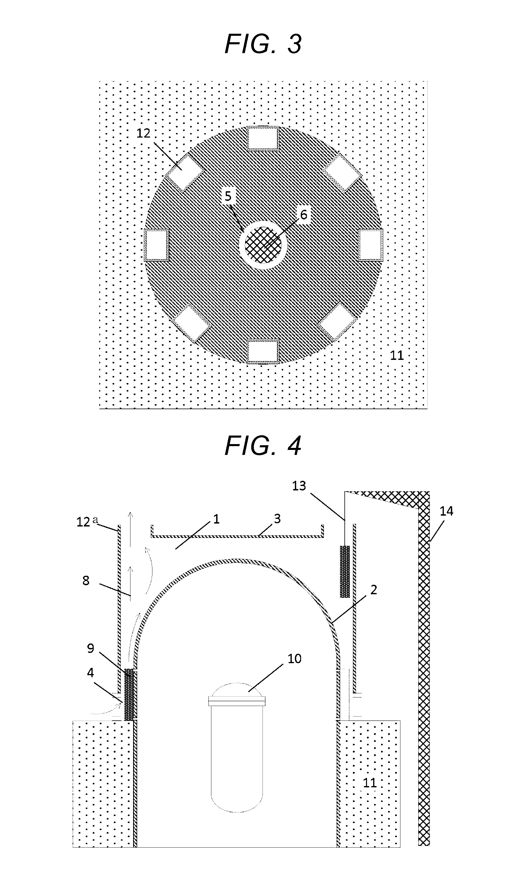
[0026]FIG. 4 is a structural view of a nuclear reactor containment vessel cooling equipment of this embodiment. In the structural view of FIG. 4, a description of portions common to those of FIG. 1 will be omitted. An air flow path 12a is installed vertically above an air-cooled heat exchanger 9. Although the hollow structure 3 of FIG. 1 is formed along the curved surface, a hollow structure 3 of this embodiment is formed into a cylindrical shape. Since a containment vessel 2 is formed into a semi-circular shape, an interval (annulus part) between the hollow structure 3 and the containment vessel 2 is wide at a ceiling peripheral part as compared with a ceiling center part.
[0027]FIG. 5 is a view of the nuclear reactor containment vessel cooling equipment of this embodiment when seen from above. A flow path sectional area of the air flow path 12a is set to be larger than at least a sectional area of the air-cooled heat exchanger when seen from above. The atmosphere flowing in from a ...
embodiment 3
[0029]FIG. 6 is a structural view of a nuclear reactor containment vessel cooling equipment of this embodiment. In the structural view of FIG. 6, a description of portions common to those of FIG. 1 will be omitted. In the nuclear reactor containment vessel cooling equipment of this embodiment, a hollow structure 3 covering an outer periphery of a containment vessel 2 is not provided. Besides, when the nuclear reactor containment vessel cooling equipment is seen from above, eight air flow paths 12b are installed at equal intervals in the periphery of the containment vessel 2. The square column-shaped air flow paths 12b are installed vertically above air-cooled heat exchangers 9, and one of the air flow paths 12b corresponds to one of the air-cooled heat exchangers 9.
[0030]FIG. 7 is a view of the nuclear reactor containment vessel cooling equipment of this embodiment when seen from above. A flow path sectional area of the air flow path 12b is set to be larger than at least a sectional...
PUM
 Abstract
Description
Claims
Application Information