

Thermal management system for electric vehicles
- Summary
- Abstract
- Description
- Claims
- Application Information
AI Technical Summary
Benefits of technology
Problems solved by technology
Method used
Image

Examples
first embodiment
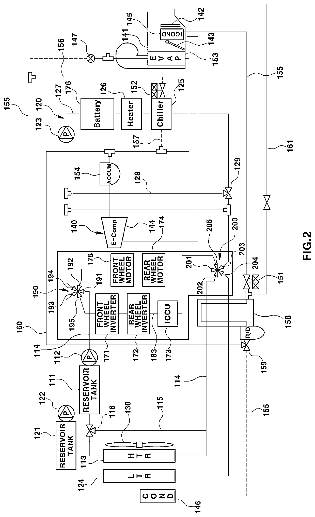
[0090]FIG. 2 is a view showing the construction of a thermal management system for electric vehicles according to the present disclosure. In FIG. 2, reference numeral 173 indicates an integrated charging control unit (ICCU) in which an on-board charger (OBC) and a low voltage DC-DC converter (LDC) configured to charge a battery are integrated.
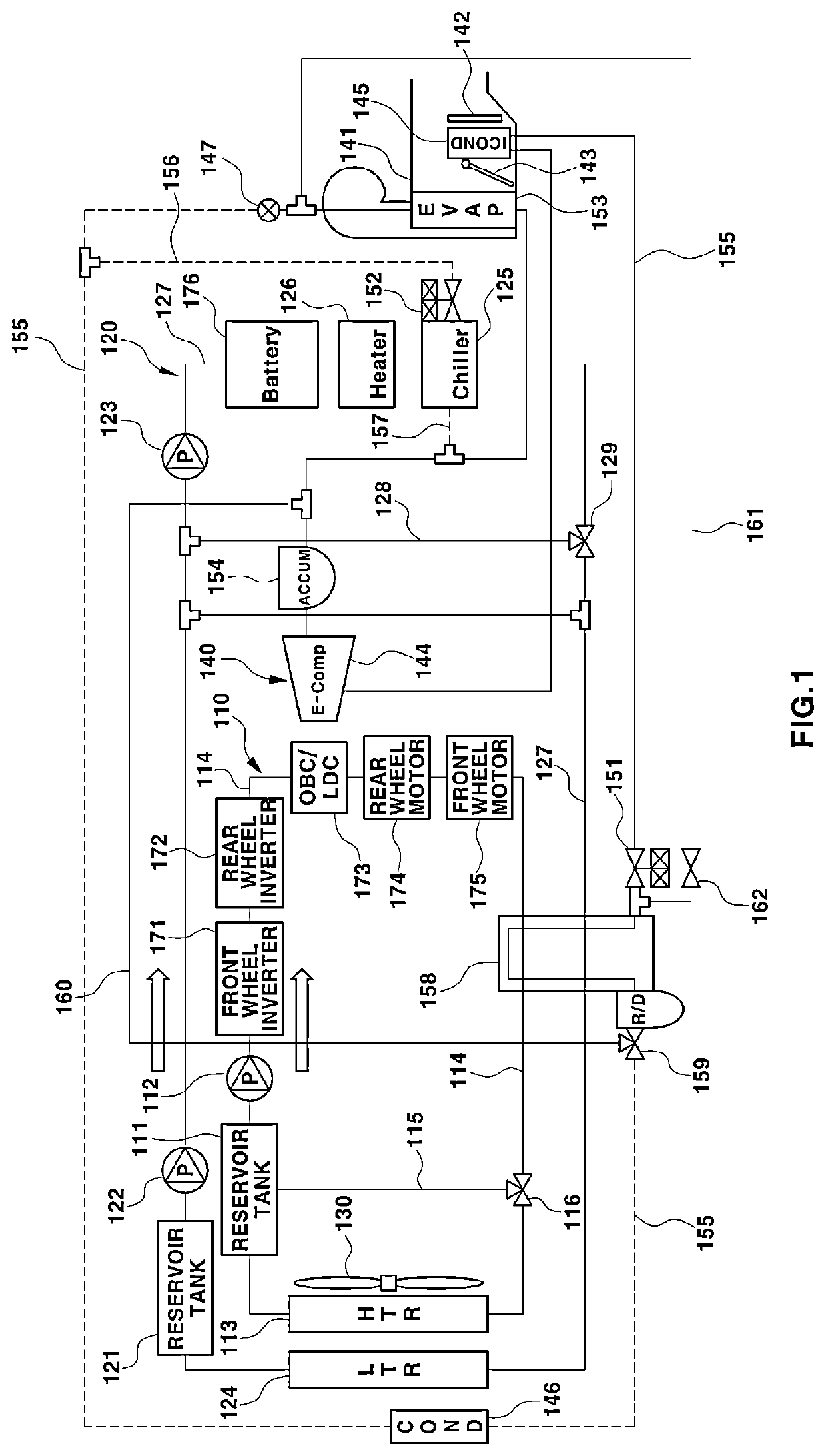
[0091]Hereinafter, the construction of the thermal management system according to the first embodiment shown in FIG. 2 is described. The construction different from that of the comparative example shown in FIG. 1 is described in full detail, and a description of the same construction as the comparative example shown in FIG. 1 is omitted. An ordinary skilled person should fully understand the portions of the construction of FIG. 2 that are identical to that of FIG. 1 from the description of the comparative example.
[0092]In the first embodiment shown in FIG. 2, the position of a third valve 116 is different from the position of the third valve 11...
second embodiment
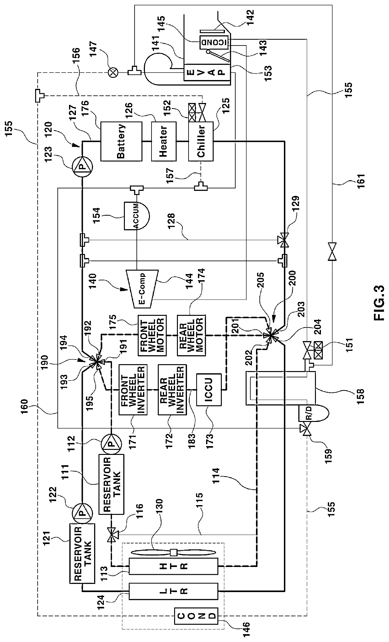
[0178]In the thermal management system a first coolant line 114 connected to a first radiator 113, a second coolant line 127 connected to a second radiator 124, and a third coolant line 183 connected thereto in parallel in a diverging form are connected to each other via the flow control valve sets 190a and 200a. Here, the flow control valve sets include two flow control valve sets configured to allow a coolant to flow between the first coolant line 114, the second coolant line 127, and the third coolant line 183, i.e., a first flow control valve set 190a and a second flow control valve set 200a.
[0179]The first flow control valve set 190a and the second flow control valve set 200a are constituted by connection lines 181 and 182 that connect the first coolant line 114 and the second coolant line 127 to each other and a plurality of valves 196, 197, 206, and 207. At this time, the first coolant line 114 at the rear end of the first radiator 113 and the second coolant line 127 at the...
PUM
 Abstract
Description
Claims
Application Information