Heavy duty tire

Active Publication Date: 2021-07-15
BRIDGESTONE CORP
View PDF0 Cites 0 Cited by
  • Summary
  • Abstract
  • Description
  • Claims
  • Application Information

AI Technical Summary

Benefits of technology

[0019]According to the heavy duty tire of the present invention as described above, an exce

Problems solved by technology

When a tire repeatedly makes contact with and separates from a road surface

Method used


Image

  • Heavy duty tire
  • Heavy duty tire
  • Heavy duty tire

Examples


Example

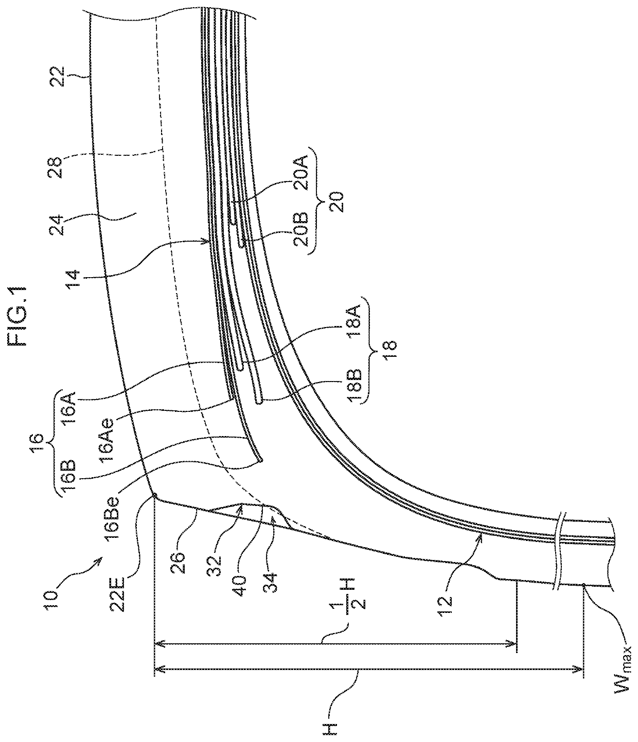
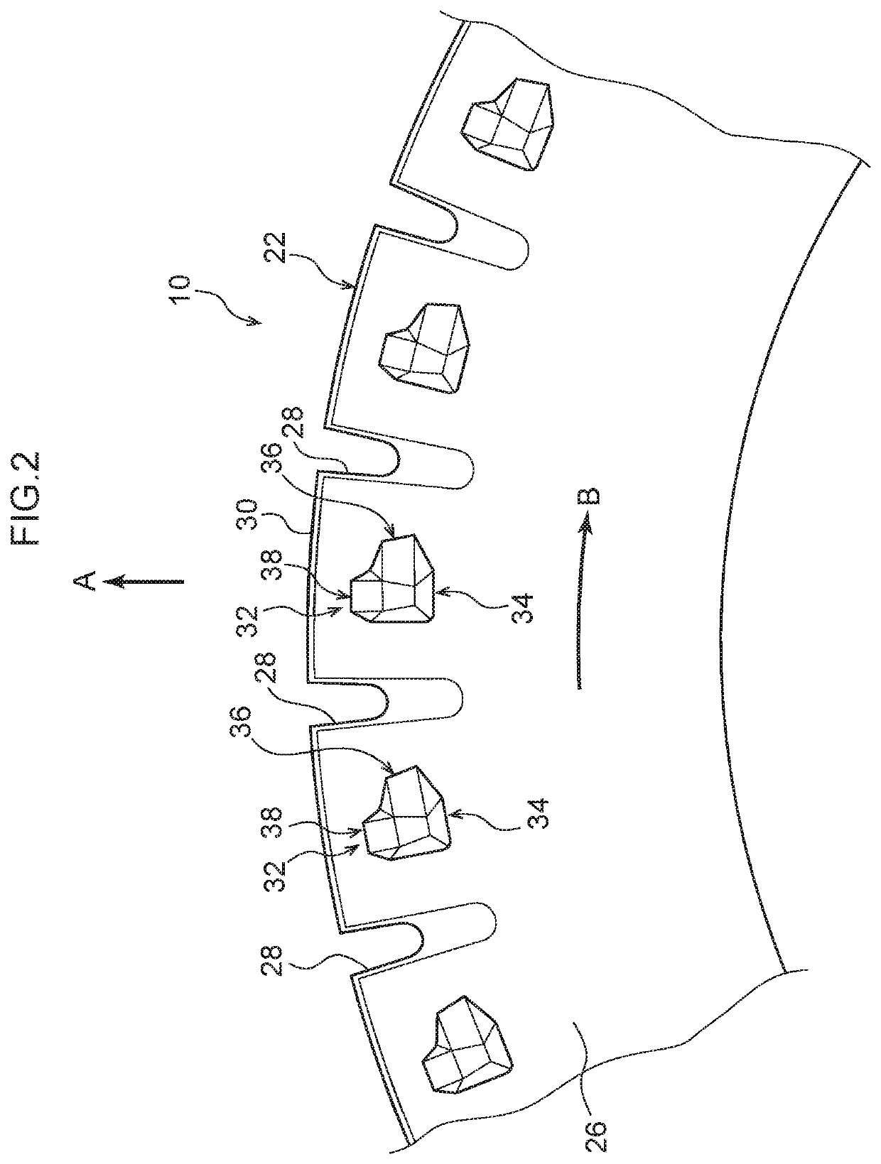
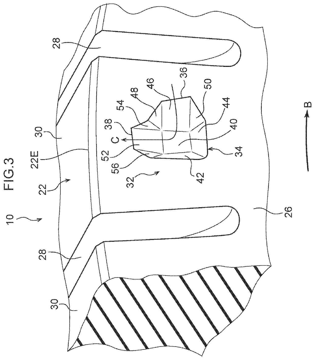
[0034]A heavy duty tire 10 according to an exemplary embodiment of the present invention is described using FIG. 1 to FIG. 5. The heavy duty tire 10 according to the present exemplary embodiment has a similar structure to a common heavy duty pneumatic tire apart from air cooling portions 32, which are described below.

[0035]As shown in FIG. 1, the heavy duty tire 10 is provided with a carcass 12 that spans between a pair of bead cores, which are not shown in the drawings.

[0036]Belt Structure

[0037]A belt 14 is disposed at a tire diameter direction outer side of the carcass 12. The belt 14 is provided with plural belt layers. More specifically, the heavy duty tire 10 according to the present exemplary embodiment is provided with a protective belt layer 16 formed of two protective belts 16A and 16B, a main interlace belt layer 18 formed of two main interlace belts 18A and 18B, and a small interlace belt layer 20 formed of two small interlace belts 20A and 20B. The protective belts 16A a...


PUM


Abstract

A heavy duty tire 10 includes a recess portion 34, a circumference-direction air entry and exit promotion portion 36 and an air-catching wall portion 42. The recess portion 34 is formed in a buttress portion 26 and opens to a tire outer side. The circumference-direction air entry and exit promotion portion 36 is disposed at one side of a floor portion 40 in a tire rotation direction and includes a slope 46 that, from the floor portion 40 toward a tire surface, gradually decreases in depth from the tire surface. The circumference-direction air entry and exit promotion portion 36 facilitates access of air toward the floor portion. The air-catching wall portion 42 is disposed at the opposite side of the floor portion 40 from the circumference-direction air entry and exit promotion portion 36. The air-catching wall portion 42 has a greater angle relative to the tire surface than the slope.

Description

TECHNICAL FIELD[0001]The present invention relates to a heavy duty tire.BACKGROUND ART[0002]In light of load-bearing capacity, size and the like of a heavy duty tire, temperatures tend to be higher in vicinities of buttress portions. When a tire repeatedly makes contact with and separates from a road surface due to running, each buttress portion warps repeatedly and generates heat. Accordingly, forming recess portions in a buttress portion and allowing air to flow in the recess portions to cool the buttress portion can be considered. Tires in which recess portions are formed in a buttress portion include, for example, the tire recited in Japanese Patent Application National Publication No. 2009-542528.SUMMARY OF INVENTIONTechnical Problem[0003]When recess portions are formed in a buttress portion, cooling of the buttress portion to some extent is enabled. However, when a carried load is large, warping increases and heat generation increases. Consequently, improvements in cooling per...

Claims


Application Information

Patent Timeline
IPC IPC(8): B60C9/18B60C11/01
CPCB60C9/18B60C2200/06B60C2011/013B60C11/01B60C9/2006B60C2009/2016B60C2009/2019B60C11/0311
Inventor NAKASATO, REOSATO, TAIKI
Owner BRIDGESTONE CORP
Why Eureka
Try Eureka