Cooling apparatus of piston and control method thereof

Active Publication Date: 2021-04-15
HYUNDAI MOTOR CO LTD +1
View PDF0 Cites 1 Cited by
  • Summary
  • Abstract
  • Description
  • Claims
  • Application Information

AI Technical Summary

Benefits of technology

[0023]And by maintaining the filling ratio in the cooling gallery of the piston at a

Problems solved by technology

However, conventionally, there is only one oil jet injecting cooling oil into the cooling gallery of the piston.
Due to this, the amount of cooling oil flowing through the cooling gallery increases, and the cooling efficiency of the piston is deteriorated.
Conversely, if the oil jet is designed based on when the engine speed is

Method used


Image

  • Cooling apparatus of piston and control method thereof
  • Cooling apparatus of piston and control method thereof
  • Cooling apparatus of piston and control method thereof

Examples


Example

[0029]The present disclosure will be described more fully hereinafter with reference to the accompanying drawings, in which exemplary embodiments of the disclosure are shown. As those skilled in the art would realize, the described embodiments may be modified in various different ways, all without departing from the spirit or scope of the present disclosure.

[0030]The drawings and description are to be regarded as illustrative in nature and not restrictive, and like reference numerals designate like elements throughout the specification.

[0031]Also, the size and thickness of each element are arbitrarily shown in the drawings, but the present disclosure is not necessarily limited thereto, and in the drawings, the thickness of layers, films, panels, regions, etc., are exaggerated for clarity.

[0032]Hereinafter, a cooling apparatus of a piston according to an exemplary embodiment of the present disclosure is described in detail reference to the drawings.

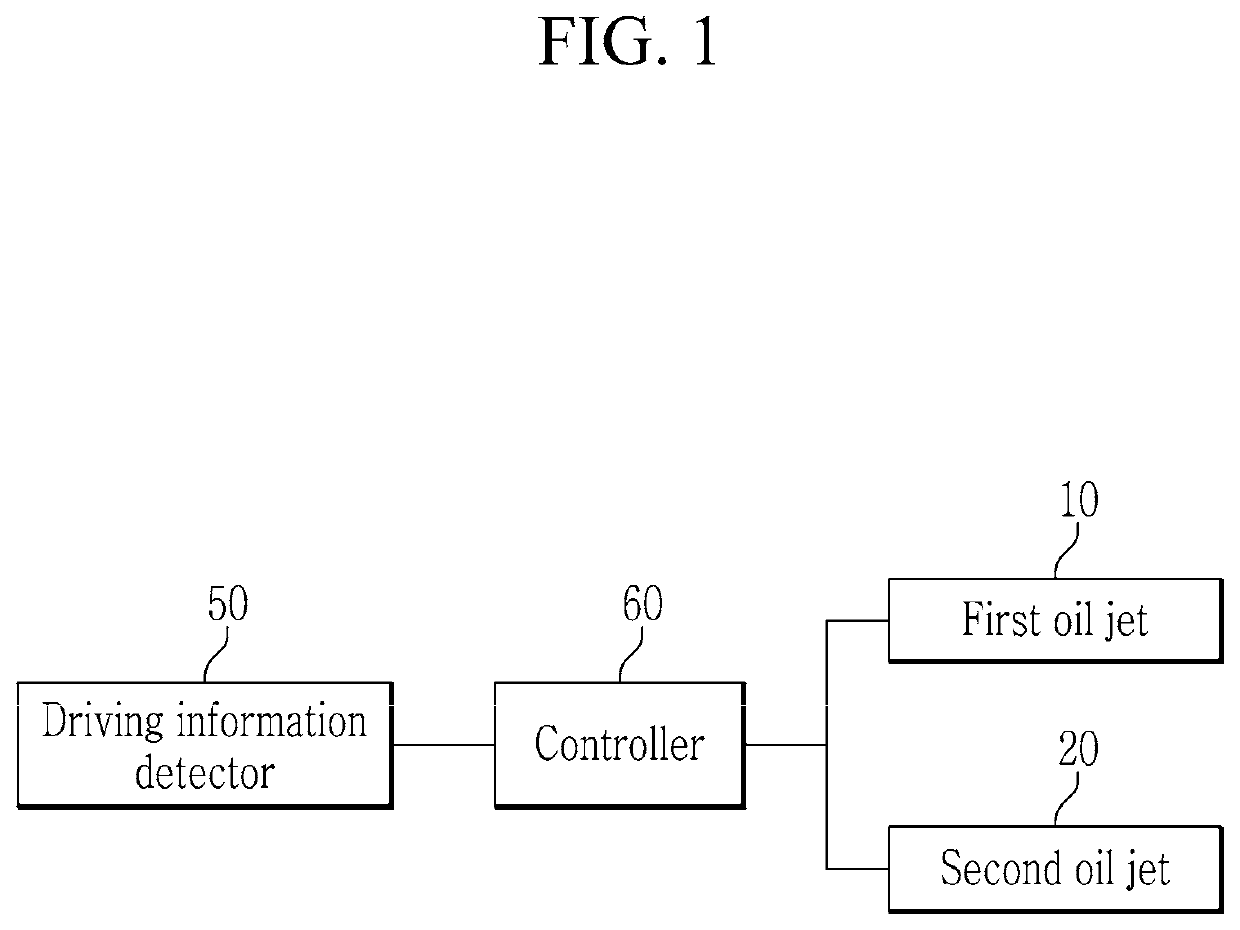
[0033]FIG. 1 is a block diagram ill...


PUM


Abstract

A cooling apparatus of a piston according to an exemplary embodiment of the present disclosure may include a piston configured to be formed with a cooling gallery, an inlet fluidly communicated with the cooling gallery, and an outlet fluidly communicated with the cooling gallery, therein, a first oil jet configured to inject cooling oil into the inlet, and a second oil jet configured to inject cooling oil into the outlet.

Description

CROSS REFERENCE TO RELATED APPLICATIONS[0001]This application claims priority to and the benefit of Korean Patent Application No. 10-2019-0127696 filed in the Korean Intellectual Property Office on Oct. 15, 2019, the entire contents of which are incorporated herein by reference.BACKGROUND(a) Field[0002]The present disclosure relates to a cooling apparatus of a piston and a method thereof. More particularly, the present disclosure relates to a cooling apparatus of a piston equipped with a plurality of oil jets that inject cooling oil of different flow rates into a cooling gallery in the piston and a control method thereof.(b) Description of the Related Art[0003]In general, a piston cooling oil jet (PCJ: piston cooling oil jet) is a device for maintaining the heat resistance and durability of a piston by lowering the temperature of the piston exposed to high temperature and high pressure by injecting cooling oil into the piston.[0004]In order to improve the cooling efficiency of the p...

Claims


Application Information

Patent Timeline
IPC IPC(8): F01P3/10F02F3/18
CPCF01P3/10F01P2003/006F02F3/18F01M1/08F01P2025/04F01P2025/62F01P2025/64F01M1/16F01P3/08
Inventor LEE, TAE WONCHO, JAE MANBAEK, HONG KIL
Owner HYUNDAI MOTOR CO LTD
Why Eureka
Try Eureka