
Cylinder head

Active Publication Date: 2022-03-10
HYUNDAI MOTOR CO LTD +1
View PDF0 Cites 0 Cited by
  • Summary
  • Abstract
  • Description
  • Claims
  • Application Information

AI Technical Summary

Benefits of technology

The present invention is about improving cooling performance in the cylinder head of an engine. It is achieved by directing coolant to the combustion chamber side and the exhaust manifold side, which increases the amount of coolant introduced there. This results in better cooling performance and improved engine efficiency.

Problems solved by technology

As a result, it is difficult to intensively supply coolant to the combustion chamber side thereof.
Consequently, the temperature of a metal surface of a combustion chamber of the cylinder head is locally increased, whereby knocking occurs, which leads to unstable combustion.

Method used


Image

  • Cylinder head
  • Cylinder head
  • Cylinder head

Examples


Embodiment Construction

[0034]Reference will now be made in detail to various embodiments of the present invention(s), examples of which are illustrated in the accompanying drawings and described below. While the present invention(s) will be described in conjunction with exemplary embodiments of the present invention, it will be understood that the present description is not intended to limit the present invention(s) to those exemplary embodiments. On the other hand, the present invention(s) is / are intended to cover not only the exemplary embodiments of the present invention, but also various alternatives, modifications, equivalents and other embodiments, which may be included within the spirit and scope of the present invention as defined by the appended claims.

[0035]Hereinafter, an exemplary various exemplary embodiments of the present invention will be described in detail with reference to the accompanying drawings.

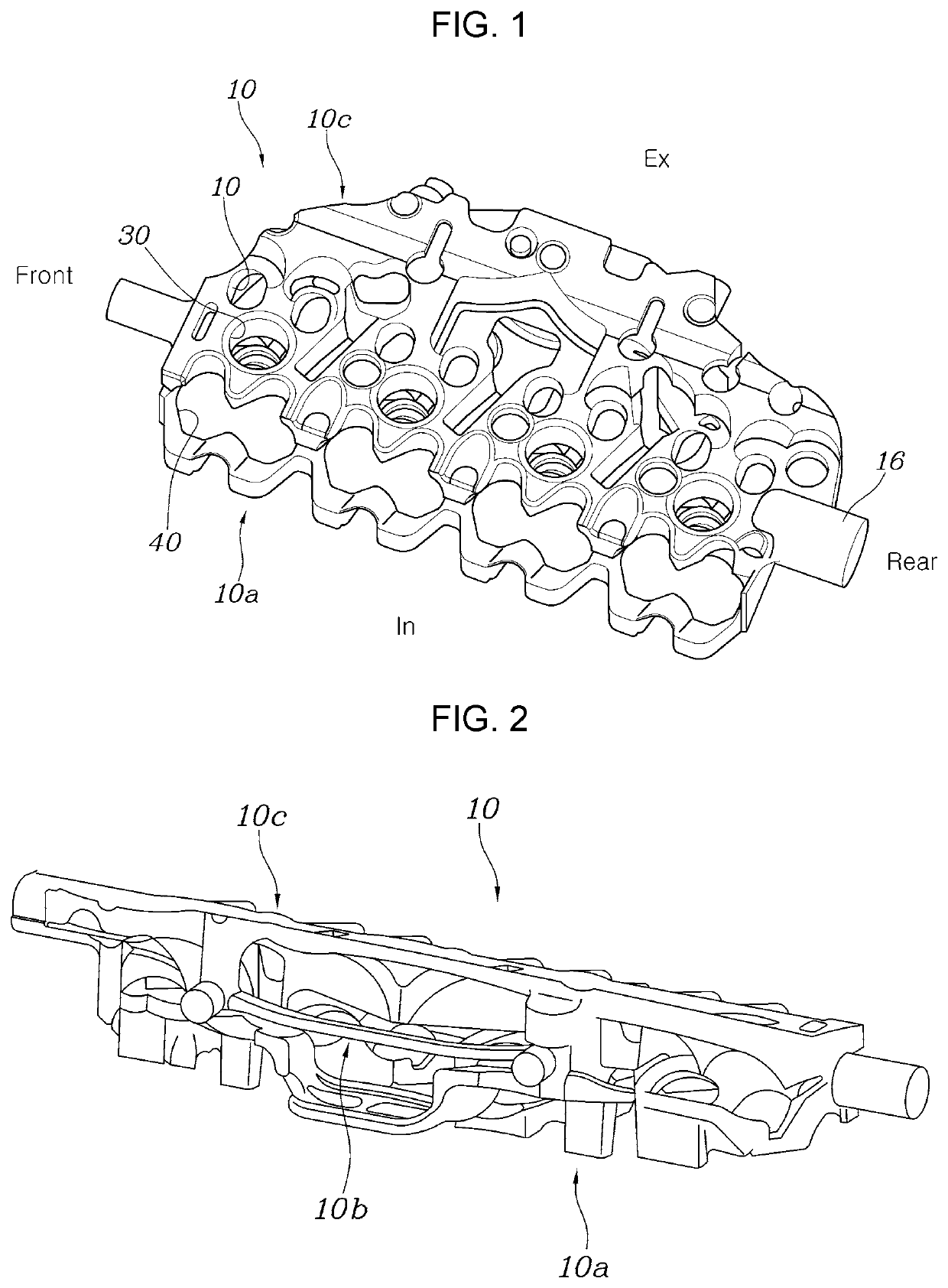
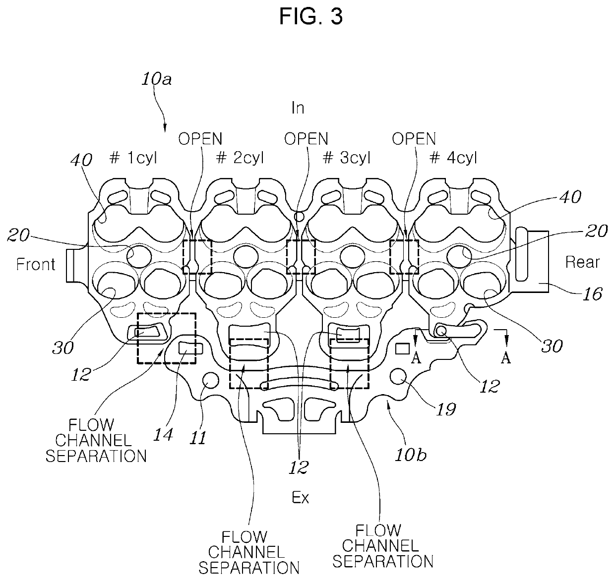
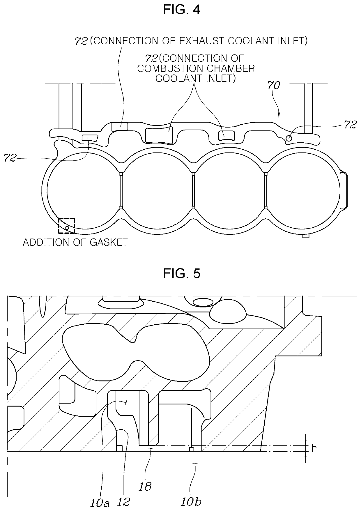
[0036]FIG. 1 is a view showing the shape of a head water jacket 10 according to various e...


PUM


Abstract

A cylinder head configured for dividing coolant introduced thereinto to a combustion chamber side and an exhaust manifold side to increase the amount of coolant introduced to the combustion chamber side, improving cooling performance, may include a head water jacket having a combustion chamber coolant inlet, through which coolant is introduced from a cylinder block to a combustion chamber side, and an exhaust coolant inlet, through which the coolant is introduced from the cylinder block to an exhaust manifold side, the combustion chamber coolant inlet and the exhaust coolant inlet being separated from each other such that the coolant introduced through the combustion chamber coolant inlet flows to the combustion chamber side in an expanded state.

Description

CROSS-REFERENCE TO RELATED APPLICATION[0001]The present application claims priority to Korean Patent Application No. 10-2020-0113119, filed on Sep. 4, 2020, the entire contents of which is incorporated herein for all purposes by this reference.BACKGROUND OF THE PRESENT INVENTIONField of the Invention[0002]The present invention relates to a cylinder head configured for dividing coolant introduced thereinto to a combustion chamber side and an exhaust manifold side to increase the amount of coolant introduced to the combustion chamber side, improving cooling performance.Description of Related Art[0003]When an engine is operated, the temperature of the engine is greatly increased due to combustion of mixed gas. To cool the engine to a temperature suitable to operate the engine, a water jacket, which is a space in which coolant flows, is formed in a cylinder block and a cylinder head.[0004]That is, coolant absorbing heat from the engine while circulating in the water jacket is introduced...

Claims


Application Information

Patent Timeline
IPC IPC(8): F02F1/16F01N13/10F02F1/40F02F1/14F01P3/20F02F1/24
CPCF02F1/16F01N13/10F02F1/40F01P2060/16F01P3/20F02F1/242F02F1/14F01N3/046F02F1/243F01P3/02F01P2003/024Y02T10/12F02F1/38
Inventor RYU, HYUN WOOKHONG, SA HOONLEE, EUN HORYU, MIN KYOUNG
Owner HYUNDAI MOTOR CO LTD
Learn More