Air-conditioner for vehicle

a technology for air conditioners and vehicles, applied in hybrid vehicles, machines/engines, transportation and packaging, etc., can solve the problems of inability to ensure the target thermal amount for heating, and inability to reduce the output of heat pumps. , to achieve the effect of reducing the output of heat pumps, improving fuel economy, and low heat generation efficiency of heat pumps

Active Publication Date: 2019-01-31
DENSO CORP
View PDF9 Cites 2 Cited by
  • Summary
  • Abstract
  • Description
  • Claims
  • Application Information

AI Technical Summary

Benefits of technology

[0010]According to the present disclosure, the air-conditioner is executed the heating thermal amount control of setting the output of the heat pump and the output of the engine according to the coolant water temperature, to ensure the target heating thermal amount. In this heating thermal amount control, the output of the heat pump and the output of the engine can be changed in response to a change in a heat generation efficiency of the heat pump according to the coolant water temperature. Thus, in a water temperature range where the heat generation efficiency of the heat pump is low, the output of the heat pump is decreased such that fuel economy is improved. Meanwhile, the output of the engine is increased, and accordingly, a heating amount of the coolant water for the engine is increased. In this manner, the target heating thermal amount can be ensured.

Problems solved by technology

A higher coolant water temperature results in a lower heat generation efficiency of the heat pump.
However, when the output of the heat pump is merely decreased with an increase in the coolant water temperature, there is a probability that a target thermal amount for heating cannot be ensured due to an insufficient heating amount of the coolant water.
Thus, depending on the engine output, the output of the heat pump cannot be decreased much even when the coolant water temperature is high.
This leads to a probability that the fuel economy cannot be effectively improved.

Method used


Image

  • Air-conditioner for vehicle
  • Air-conditioner for vehicle
  • Air-conditioner for vehicle

Examples


first embodiment

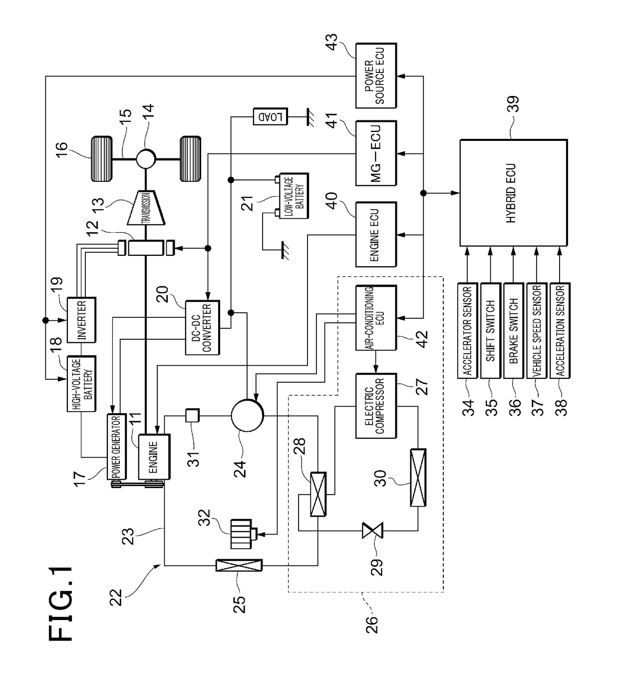
[0027]A first embodiment will be described with reference to FIGS. 1 to 4. First, an outline configuration of a control system of a hybrid vehicle will be described with reference to FIG. 1.

[0028]An engine 11 as an internal-combustion engine and a motor generator (hereinafter referred to as “MG”) 12 are mounted as a vehicle power source. Power of a crankshaft as an output shaft of the engine 11 is transmitted to a transmission 13 via the MG 12. Power of an output shaft of the transmission 13 is transmitted to wheels 16 as drive wheels via a differential gear mechanism 14 and an axle 15. The transmission 13 may be an automatic / manual transmission configured to switch a gear position in a stepwise manner among multiple gear positions, or a continuously variable transmission as CVT configured to shift gears steplessly.

[0029]A rotary shaft of the MG 12 is coupled so that the power can be transmitted between the engine 11 and the transmission 13 in a power transmission path for transmitt...

second embodiment

[0064]Next, a second embodiment will be described with reference to FIGS. 5 to 8. Note that description of portions substantially identical or similar to those of the first embodiment will be omitted or simplified, and differences from the first embodiment will be mainly described.

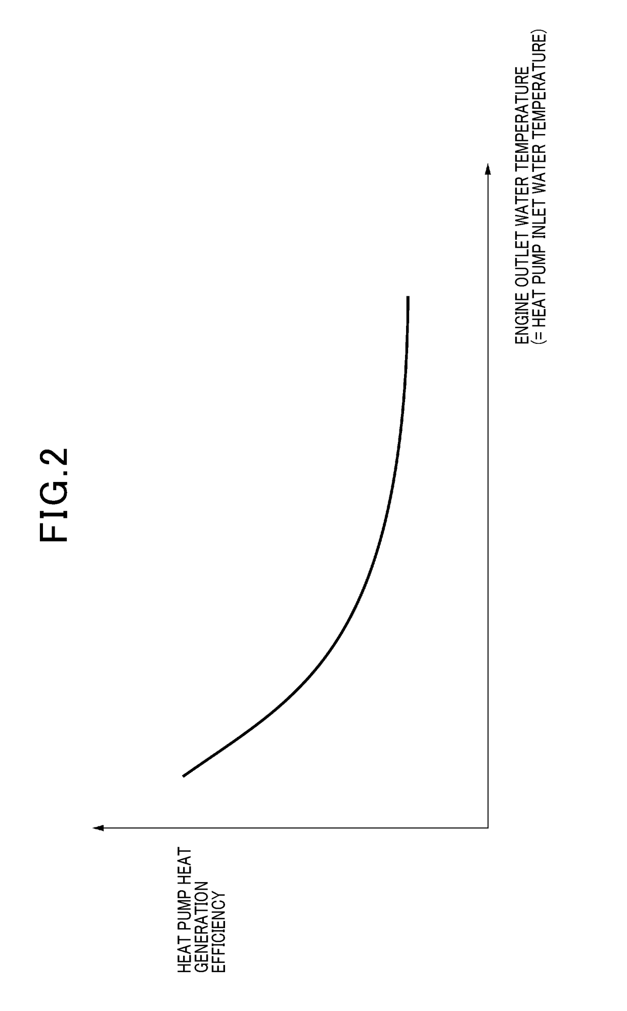
[0065]For example, a heat pump 26 also changes its heat generation efficiency depending on output as a rotation speed of an electric compressor 27, and an output range with a high heat generation efficiency changes according to an engine outlet water temperature. Considering such characteristics, a heating thermal amount control routine of FIG. 5 as described later is, in the second embodiment, executed by a hybrid ECU 39 for performing the following heating thermal amount control. In the heating thermal amount control of the second embodiment, the control of setting the output of the heat pump 26 to a value within a predetermined range set according to the engine outlet water temperature and setting the o...

third embodiment

[0078]Next, a third embodiment will be described with reference to FIGS. 9 to 14. Note that description of portions substantially identical or similar to those of the first and second embodiments will be omitted or simplified, and differences from the first and second embodiments will be mainly described.

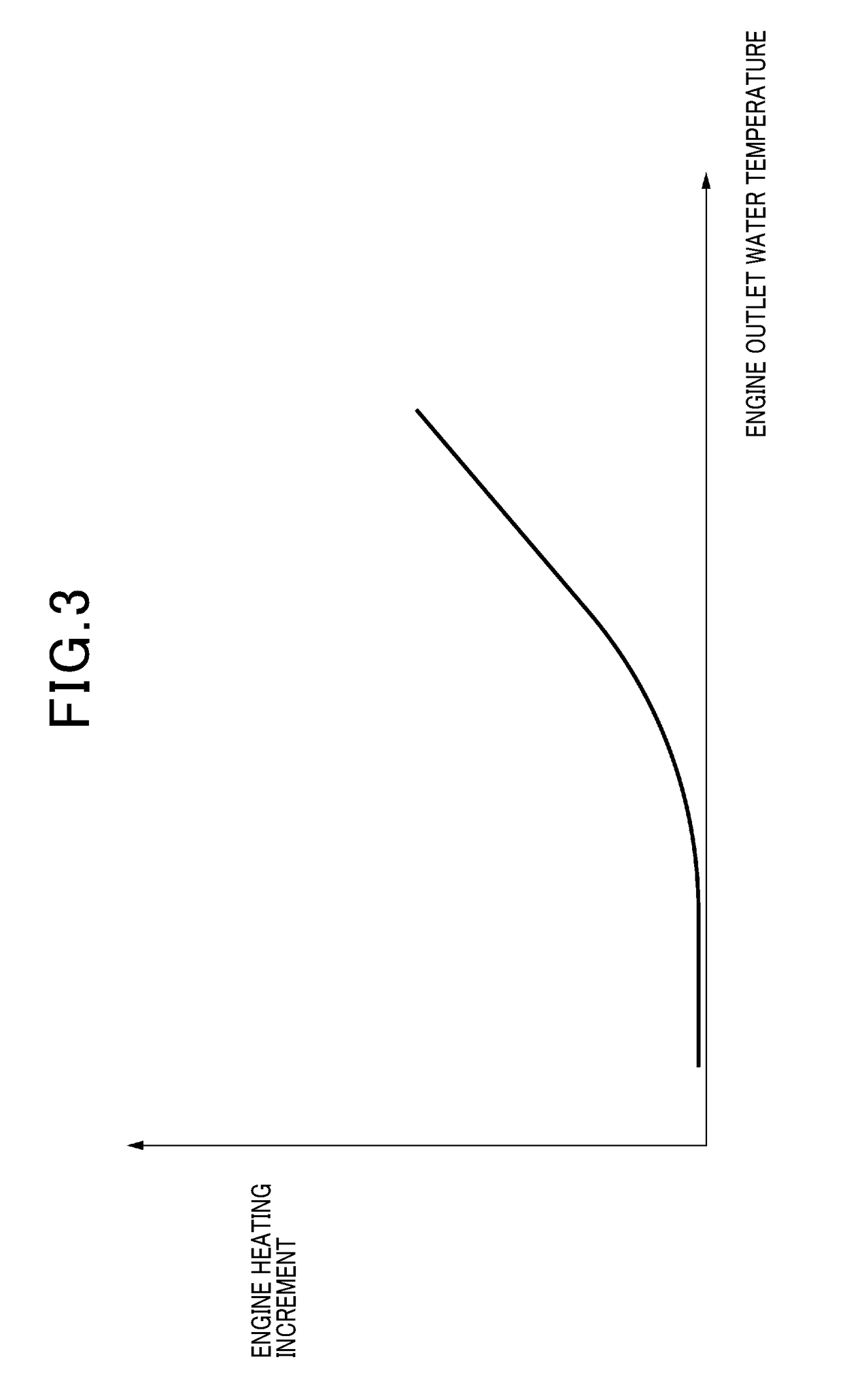
[0079]In the third embodiment, a heating thermal amount control routine of FIG. 9 as described later is executed by a hybrid ECU 39 for performing the following heating thermal amount control. In the heating thermal amount control of the third embodiment, characteristics of a heat generation efficiency of a heat pump 26 are set based on an engine outlet water temperature etc. The heat generation efficiency of the heat pump 26 is the percentage of a coolant water heating amount with respect to consumed energy of the heat pump 26. Moreover, characteristics of a power generation efficiency of an engine 11 are set. The power generation efficiency of the engine 11 is the percentage of a ...


PUM


Abstract

A heat pump and a heater core are provided at a heating coolant water circuit connected to an engine. As heating thermal amount control, the control of decreasing the output of the heat pump and increasing the output of the engine with an increase in an engine outlet water temperature detected by an engine outlet water temperature sensor, thereby ensuring a target heating thermal amount. Thus, in response to a decrease in a heat generation efficiency of the heat pump with an increase in the engine outlet water temperature, the output of the heat pump is decreased so that fuel economy can be improved while the output of the engine is increased so that the target heating thermal amount can be ensured.

Description

CROSS-REFERENCE TO RELATED APPLICATION[0001]This application claims the benefit of the priority to Japanese Patent Application No. 2016-18401 filed Feb. 2, 2016, the entire contents of which are incorporated herein by reference.TECHNICAL FIELD[0002]The present disclosure relates to an air-conditioner for a vehicle.BACKGROUND ART[0003]In recent years, a hybrid vehicle equipped with an engine and a motor as a vehicle power source has attracted attention for the reasons of societal demands such as low fuel consumption and low exhaust emission. Such a hybrid vehicle includes, for example, a vehicle configured such that EV travelling for causing the vehicle to travel by power of a motor with an engine being stopped is performed to improve fuel economy. However, when the time for operating the engine to ensure an amount of heat for heating during, e.g., the wintertime, is increased, the fuel economy has a tendency to be lowered. The amount of heat for heating is an amount of heat of coola...

Claims


Application Information

Patent Timeline
Patent Type & Authority Applications(United States)
IPC IPC(8): B60H1/03F01P11/16F01P3/20F02D29/06
CPCB60H1/034F01P11/16F01P3/20F02D29/06F01P2025/32F01P2007/146B60K6/485F01P7/164F01P2005/125F01P2050/24F01P2060/08F01P2060/14B60H1/3208B60H1/3213B60H2001/3266B60H1/32281B60K6/448Y02T10/62
Inventor OKAMOTO, TSUYOSHIWATANABE, TAKAYUKI
Owner DENSO CORP
Why Eureka
Try Eureka