
Compact mammograph and associated mammography process

a mammograph and process technology, applied in the field of mammograph and mammography process, can solve the problems of degradation of image quality, inability of prior art mammographs to reconcile and inability to compactness and image quality

Active Publication Date: 2016-06-14
GENERAL ELECTRIC CO
View PDF30 Cites 6 Cited by
  • Summary
  • Abstract
  • Description
  • Claims
  • Application Information

AI Technical Summary

Benefits of technology

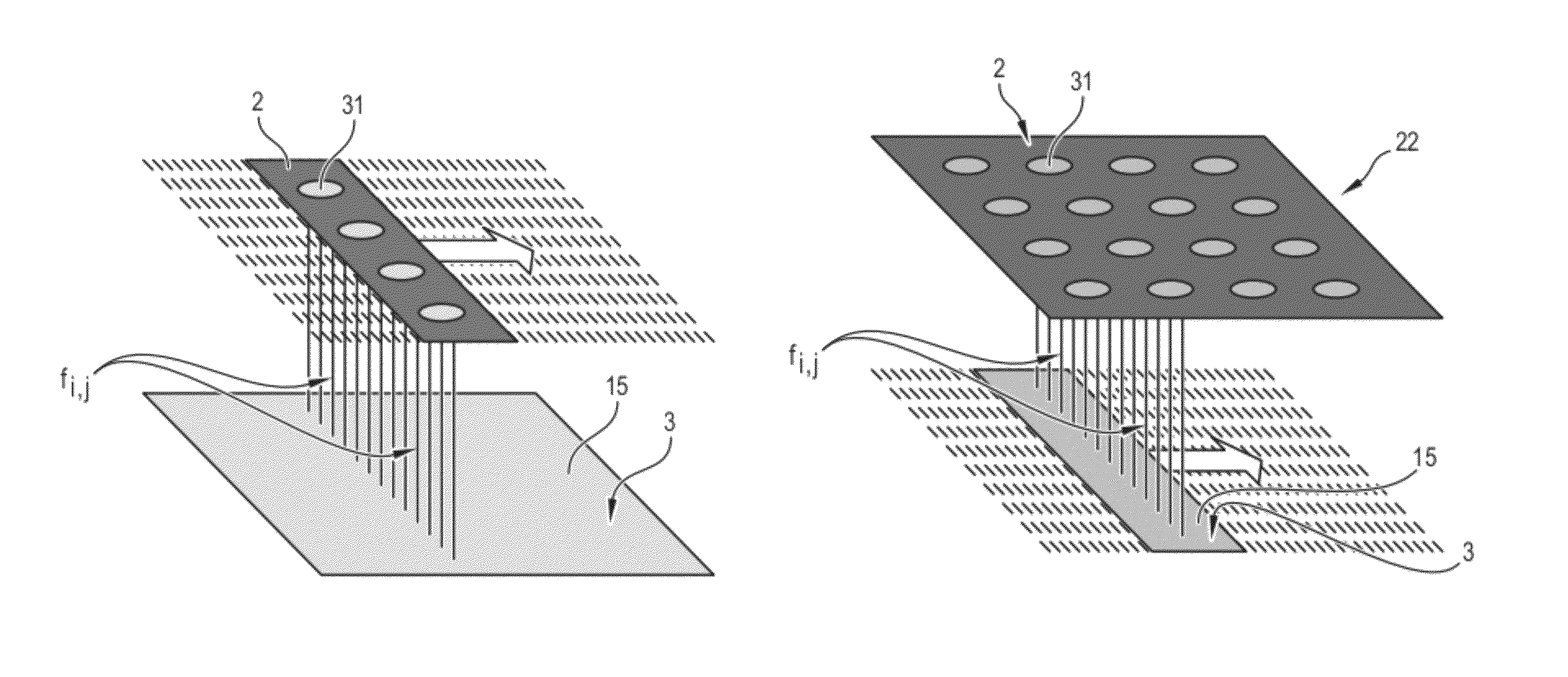
[0013]According to an embodiment of the present invention, a mammograph is provided. The mammograph includes a source of X-rays; a detector of X-rays, the source being configured to emit at least one beam of X-rays to the detector; and an optic control device configured to control the direction of X-rays emitted by the source such that the X-rays emitted by the source are substantially parallel to one another.
[0105]In addition, the invention proposes a mammograph reducing the risk of collision of a patient with the source of X-rays, given that the source can be located, under the head of the patient, without the image of the breast being truncated.
[0108]Another advantage of the invention is to enable reduction in thermal output of the source, especially in the case where sub-sets of X-ray beams are successively emitted, as described previously.
[0013]According to an embodiment of the present invention, a mammograph is provided. The mammograph includes a source of X-rays; a detector of X-rays, the source being configured to emit at least one beam of X-rays to the detector; and an optic control device configured to control the direction of X-rays emitted by the source such that the X-rays emitted by the source are substantially parallel to one another.

Problems solved by technology

As a consequence, prior art devices are not very compact.
But a large-sized emission focal spot, associated with a small distance between the detector and the source, causes degradation of the image quality by the appearance of blurring in the prior art mammographs, apart from truncation of the breast in the image previously mentioned.
Prior art mammographs cannot therefore simultaneously reconcile compactness and image quality.
Due to the position of the patient under compression or to the pressure exerted by the protective cover on the patient, the breast of the patient tends to also be pushed back from the imaging zone, the disadvantage of which is to reduce the portion of the breast viewed by the mammograph, as well as creating a source of discomfort for the patient.

Method used


Image

  • Compact mammograph and associated mammography process
  • Compact mammograph and associated mammography process
  • Compact mammograph and associated mammography process

Examples


Embodiment Construction

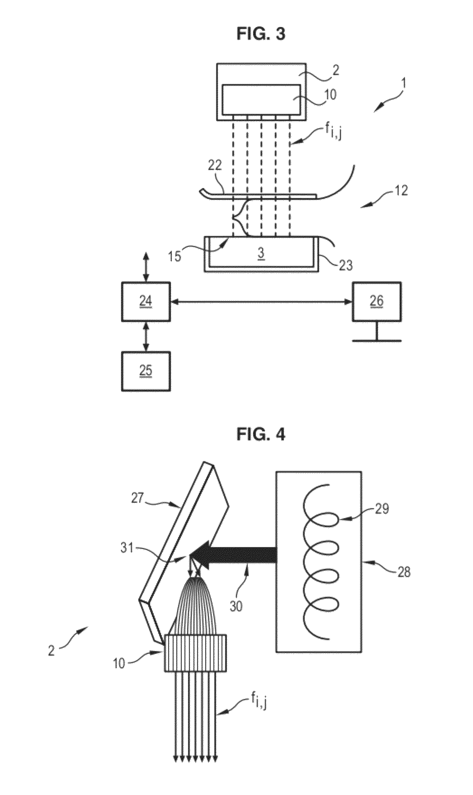
[0025]FIG. 3 is a schematic representation of a mammograph 1 according to an exemplary embodiment of the present invention. The mammograph 1 comprises a source 2 of X-rays and a detector 3 of X-rays. The source 2 of X-rays is capable of emitting at least one beam fi,j of X-rays to the detector 3, for conducting mammography of a patient 12.

[0026]The mammograph 1 comprises an upper plate 22, a so-called compression pad, and a lower block 23. The upper plate 22 is mobile in vertical translation to compress the breast of the patient 12 against the lower block 23. Alternatively, or in addition, it is the lower block which is mobile for compressing the breast.

[0027]The detector 3 comprises a detection surface 15 turned to the beam fi,j, under the breast of the patient 12. The detector 3 is, for example, an image sensor with semi-conductors comprising, for example, caesium iodide phosphore (scintillater) on a matrix of transistor / photodiode of amorphous silicon. Other adequate detectors in...


PUM


Abstract

A mammograph is provided. The mammograph includes a source of X-rays; a detector of X-rays, the source being configured to emit at least one beam of X-rays to the detector; and an optic control device configured to control the direction of X-rays emitted by the source such that the X-rays emitted by the source are substantially parallel to one another.

Description

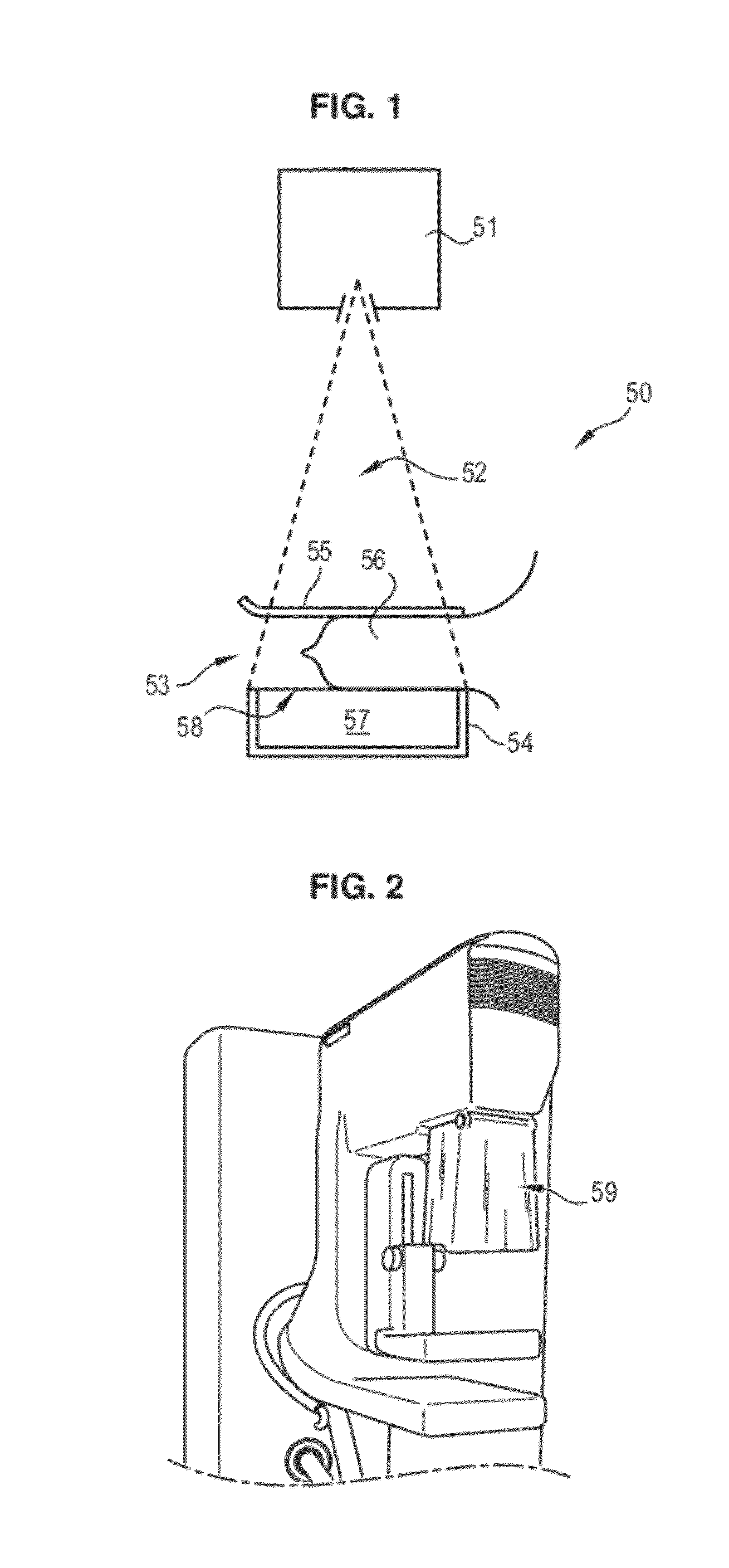
BACKGROUND OF THE INVENTION[0001]1. Field of the Invention[0002]Embodiments of the present invention relate to a mammograph and a mammography process.[0003]2. Description of the Prior Art[0004]Mammography is a radiography technique for studying the breast of a patient for clinical and / or interventional purposes. It can especially detect early-stage breast cancer in a patient, and / or repair lesions leading up to surgical intervention.[0005]FIG. 1 schematically illustrates a mammograph 50 in an embodiment known from the prior art. The mammograph 50 comprises a source 51 of X-rays capable of emitting a beam 52 of X-rays to a frame 53 comprising a lower block 54, on which the breast 56 of a patient rests, and an upper plate 55, a so-called compression pad. The upper plate 55 is mobile in vertical translation so as to compress the breast 56 of the patient against the lower block 54. The lower block 54 also comprises a detector 57, whereof the detection surface 58 is turned to the beam 52...

Claims


Application Information

Patent Timeline
Patent Type & Authority Patents(United States)
IPC IPC(8): A61B6/00H01J35/06B82Y10/00G21K1/06A61B6/08
CPCA61B6/482A61B6/502A61B6/588B82Y10/00G21K1/06H01J35/06A61B6/08G21K2201/061G21K2201/064H01J2235/068A61B6/4021H01J35/064
Inventor LEE, SUSANNE MADELINEBOUDIER, AURELIEMULLER, SERGE LOUIS WILFRID
Owner GENERAL ELECTRIC CO
Learn More