
Pressure roller for fixing apparatus, fixing apparatus and image forming apparatus

Active Publication Date: 2020-03-05
CANON KK
View PDF3 Cites 2 Cited by
  • Summary
  • Abstract
  • Description
  • Claims
  • Application Information

AI Technical Summary

Benefits of technology

This patent is about a pressure roller for a fixing apparatus used in image forming devices. The technical effects of the patent are to achieve both a moderate softness of the elastic layer and to suppress the temperature rise of the non-passing portion.

Problems solved by technology

However, when the pressure roller having a low thermal conductivity is used, in the case where a recording material having a smaller width than the maximum usable width is used as the recording material, non-passing portion temperature rise easily occurs.
The thermal conductive filler has an effect of enhancement of the thermal conductivity, but when the content ratio is high, the softness of the elastic layer is impaired.
However, the low hardness rubber has a low strength, and therefore, the durability is sometimes insufficient.
Further, it has been found that a necessary fixing nip cannot be sometimes secured in the non-porous heat accumulating layer at the time of a high-speed operation in which pressurization and release are performed at a high speed.
This is because the deformation velocity of the rubber at the fixing nip is insufficient for the formation of the nip and therefore the rubber is not sufficiently transformed during the passing of the fixing nip.

Method used


Image

  • Pressure roller for fixing apparatus, fixing apparatus and image forming apparatus
  • Pressure roller for fixing apparatus, fixing apparatus and image forming apparatus
  • Pressure roller for fixing apparatus, fixing apparatus and image forming apparatus

Examples


first embodiment

1. Image Forming Apparatus

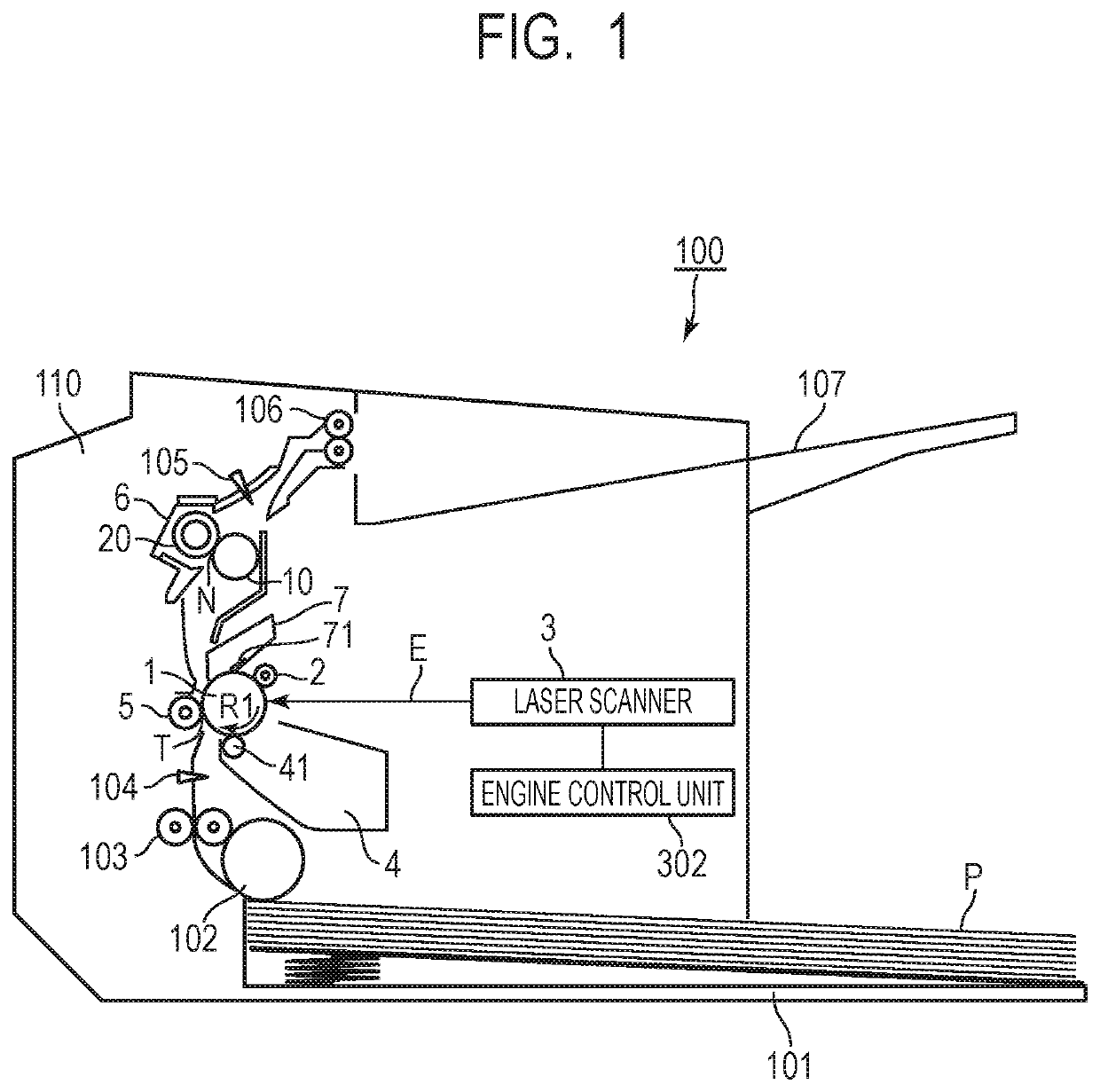
[0021]FIG. 1 is a schematic sectional view of an image forming apparatus 100 in the embodiment. The image forming apparatus 100 in the embodiment is a laser printer using an electrophotographic technique. Herein, a direction roughly orthogonal to a conveying direction of a later-described recording material P is also referred to as a “longitudinal direction”. The longitudinal direction is roughly parallel to a rotation axis direction of a later-described photosensitive drum 1 and a pressure roller 20 of a later-described fixing apparatus 6.

[0022]The image forming apparatus 100 includes a photosensitive drum 1 that is a drum-shaped (cylindrical) rotatable photoreceptor (electrophotographic photoreceptor) as an image supporting body configured to support a toner image. The photosensitive drum is adapted by providing a photosensitive material such as an organic photosemiconductor (OPC), amorphous selenium and amorphous silicon, on a cylinder-shaped drum base b...

experiment examples

8. Configuration of Experiment Examples

[0100]Next, the present invention will be further specifically described with experiment examples.

[0101]

[0102]The pressure roller 20 in Experiment Example A1 was produced as follows.

[0103]Step of Preparing Liquid Composition for Outer Elastic Layer (First Step)

[0104]The liquid composition for the outer elastic layer was prepared by blending 1 pts.wt. of the silane coupling agent (methacryloxypropyl trimethoxy silane) in 100 pts.wt. of the liquid silicone rubber, further blending 5 pts.wt. of the resin microballoon (trade name: F80-DE manufactured by Matsumoto Yushi-Seiyaku Co., Ltd.) having an average particle diameter of 100 μm, and sufficiently performing stirring.

[0105]Step of Forming Outer Elastic Layer (Second Step)

[0106]In the way described above with reference to FIG. 4 and FIG. 5, the formed body in which the fluorine resin tube 75 fixed to the outer die 71 and the outer elastic layer 79 were integrated was obtained. On this occasion, t...


PUM


Abstract

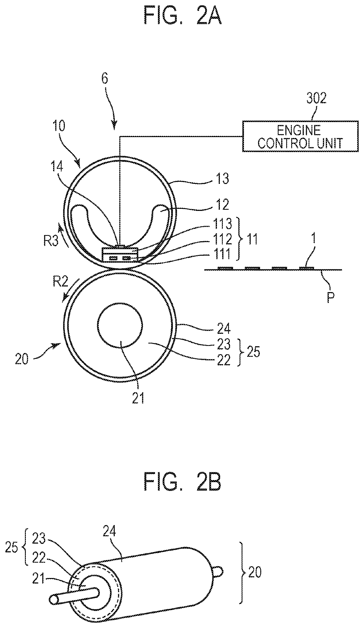
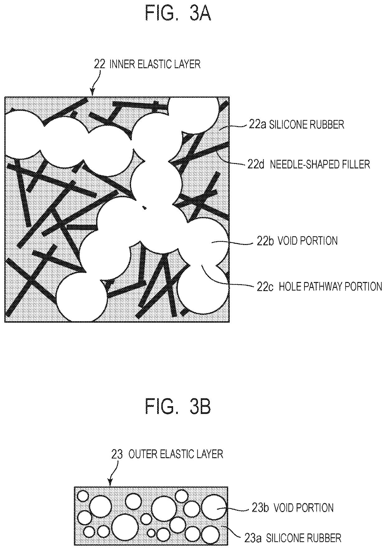
A pressure roller, and the pressure roller to be used in a fixing apparatus of in an image forming apparatus, the fixing apparatus configured to heat a toner image formed on a recording material and fix the toner image on the recording material, the pressure roller including a first elastic layer, and a second elastic layer provided on an outside of the first elastic layer, wherein a thermal conductivity of the first elastic layer is higher than a thermal conductivity of the second elastic layer, and wherein the first elastic layer contains a plurality of void portions, hole pathway portions joining the plurality of void portions to each other, and a needle-shaped high thermal conductive filler.

Description

BACKGROUND OF THE INVENTIONField of the Invention[0001]The present invention relates to a pressure roller for a fixing apparatus that is equipped in an image forming apparatus using one of an electrophotographic technique and an electrostatic recording technique, such as a copier, a printer (a laser printer, an LED printer and the like) and a facsimile apparatus, a fixing apparatus equipped with the pressure roller, and an image forming apparatus.Description of the Related Art[0002]In an image forming apparatus using an electrophotographic technique or the like, an image heating apparatus such as a fixing apparatus configured to heat a recording material supporting the toner image and fix the toner image on the recording material is used. For example, the fixing apparatus includes a heating member (fixing member) to contact with an unfixed toner on the recording material and a pressure roller to tightly contact with the heating member and form a nip portion (fixing nip). Then, the f...

Claims


Application Information

Patent Timeline
IPC IPC(8): G03G15/20
CPCG03G15/2057G03G15/2064G03G15/206
Inventor TAGUCHI, SHOMURATA, NAOFUMIMATSUNAKA, KATSUHISAARAI, YUTAKA
Owner CANON KK
Learn More