
Method and apparatus for wire handling and embedding on and within 3D printed parts

Active Publication Date: 2017-03-02
BOARD OF RGT THE UNIV OF TEXAS SYST
View PDF4 Cites 97 Cited by
  • Summary
  • Abstract
  • Description
  • Claims
  • Application Information

AI Technical Summary

Benefits of technology

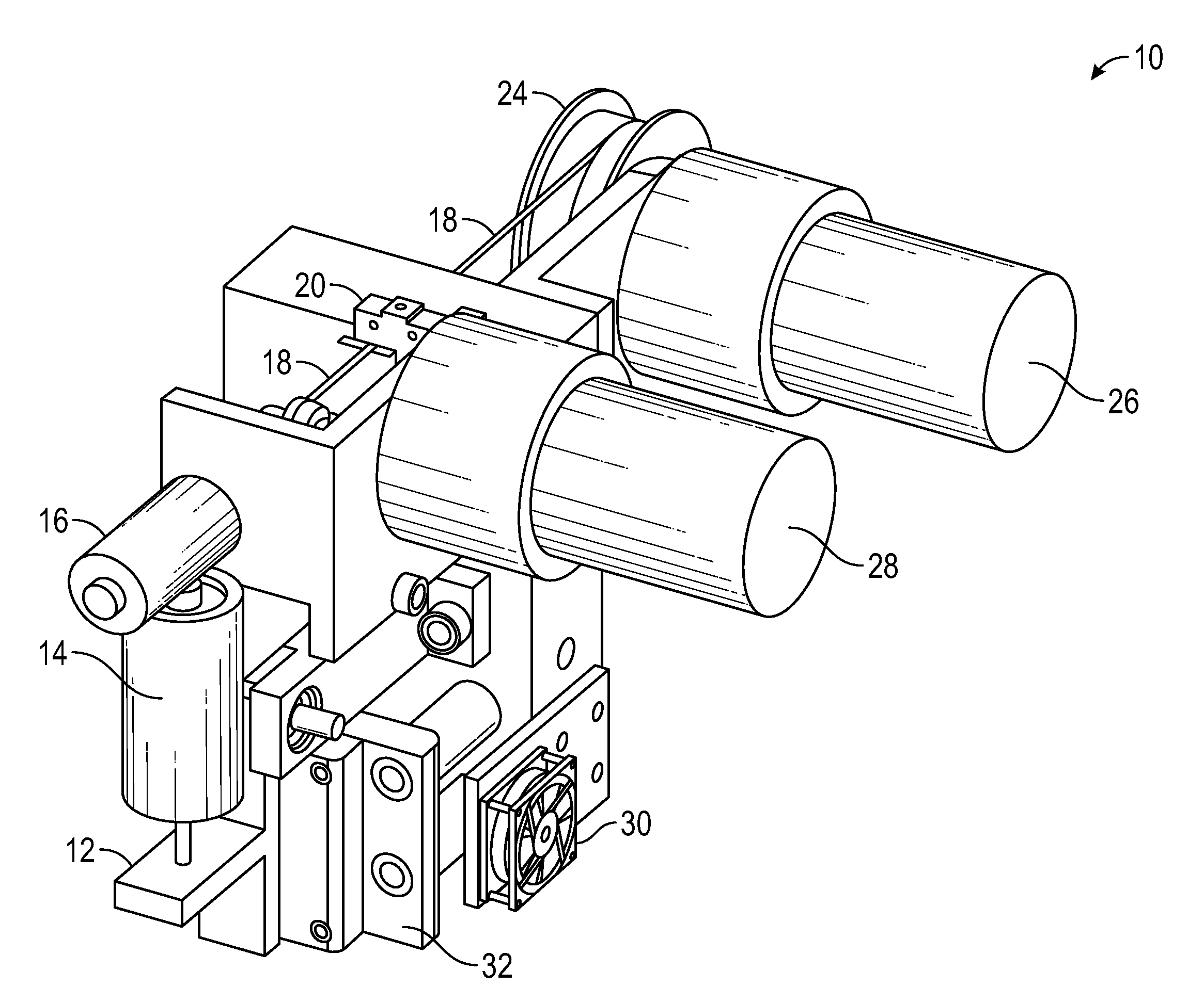
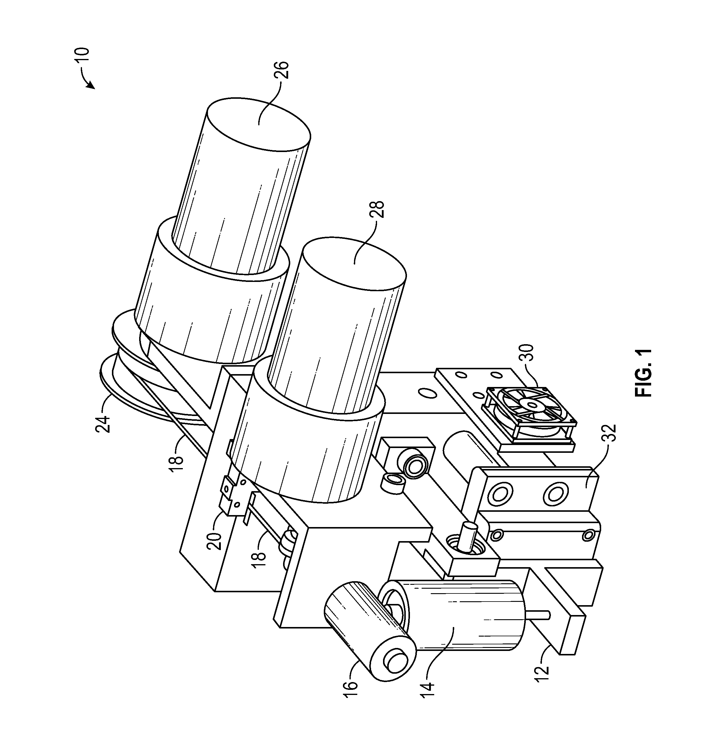
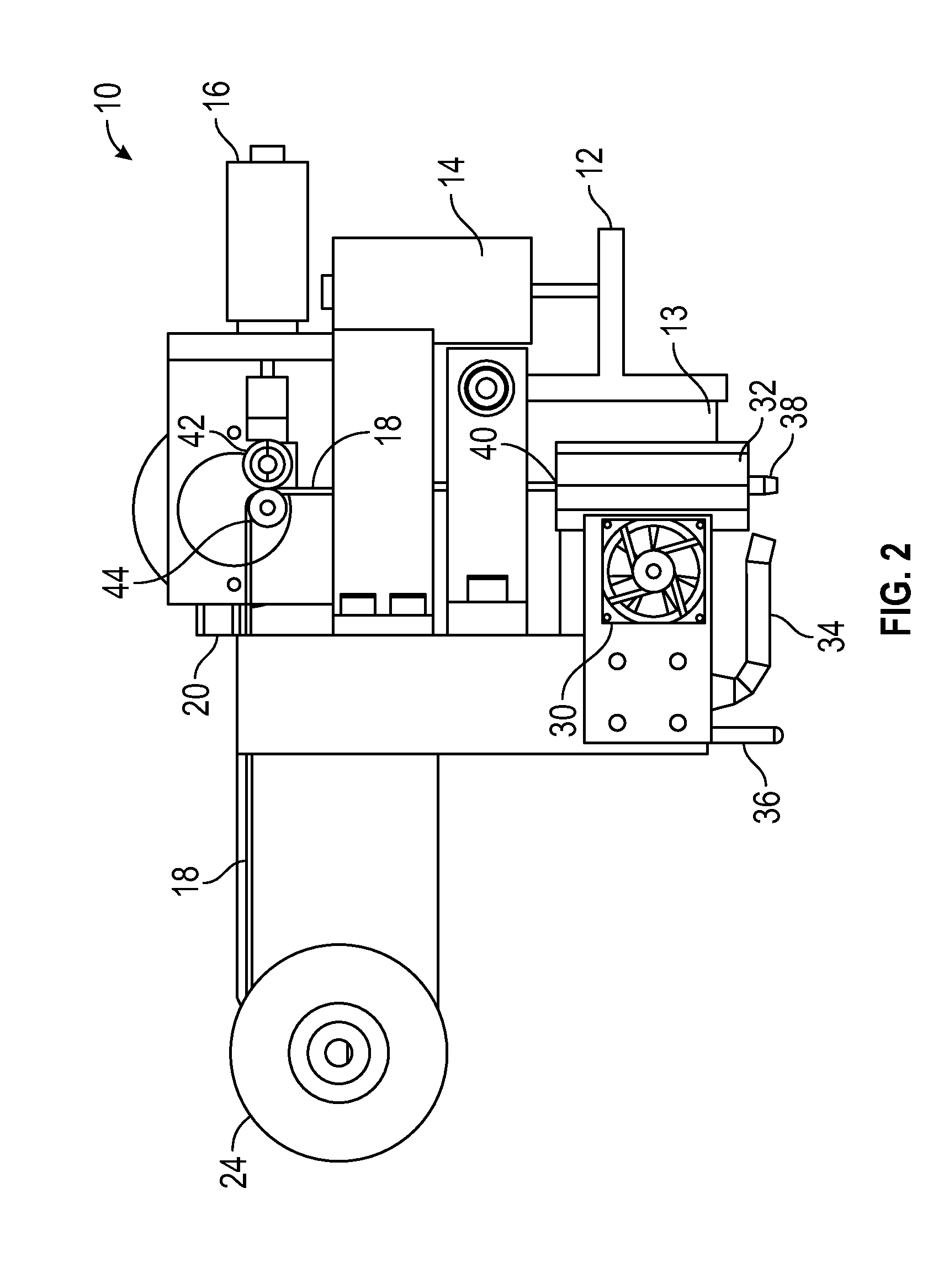
The patent describes an apparatus, system, and method for manufacturing three-dimensional products using a direct wire embedding head. This head can be fixed on an automation motion system and create embedded wire patterns on the surface of a 3D part. A sensor can be used to measure the distance between the embedding head and the surface and adjust the position of the embedding head accordingly to ensure successful embedding results. The apparatus can create interconnections between electronic, electromagnetic, or mechanical components on the surface of the part. This invention automates the process of creating complex wire patterns on 3D parts, which can save time and improve efficiency.

Problems solved by technology

Opportunities arise when this access is provided.

Method used


Image

  • Method and apparatus for wire handling and embedding on and within 3D printed parts
  • Method and apparatus for wire handling and embedding on and within 3D printed parts
  • Method and apparatus for wire handling and embedding on and within 3D printed parts

Examples


Embodiment Construction

[0028]The particular values and configurations discussed in these non-limiting examples can be varied and are cited merely to illustrate at least one embodiment and are not intended to limit the scope thereof.

[0029]The embodiments will now be described more fully hereinafter with reference to the accompanying drawings, in which illustrative embodiments of the invention are shown. The embodiments disclosed herein can be embodied in many different forms and should not be construed as limited to the embodiments set forth herein; rather, these embodiments are provided so that this disclosure will be thorough and complete, and will fully convey the scope of the invention to those skilled in the art. For example, preferred and alternative embodiments are disclosed herein.

[0030]Additionally, like numbers refer to identical, like, or similar elements throughout, although such numbers may be referenced in the context of different embodiments. As used herein, the term “and / or” includes any an...


PUM

PropertyMeasurementUnit
Distanceaaaaaaaaaa
Selectivityaaaaaaaaaa

Abstract

An apparatus, system, and method for automatically dispensing and embedding components into three-dimensional parts. In an example embodiment, a direct wire embedding head can be fixed on an automation motion system. The direct wire embedding head begins and terminates an embedded wire pattern on a layer or on a surface of a three-dimensional part in order to automatically create the embedded wire pattern. A sensor is located on an embedding surface wherein the embedded wire pattern is embedded. The sensor can measure the distance between the direct wire embedding head and the embedding surface. A predefined distance can be maintained to ensure successful embedding results for the embedded wire pattern by automatically adjusting a position of the direct wire embedding head in response to feedback from the sensor.

Description

CROSS-REFERENCE TO PROVISIONAL APPLICATION[0001]This nonprovisional patent application claims the benefit under 35 U.S.C. §119(e) of U.S. Provisional Patent Application Ser. No. 62 / 209,067 filed on Aug. 24, 2015, entitled “Method and Apparatus for Wire Handling and Embedding On and Within 3D Printed Parts”. U.S. Provisional Patent Application Ser. No. 62 / 209,067 is incorporated herein by reference in its entirety.TECHNICAL FIELD[0002]Embodiments are related to the manufacturing of three-dimensional products with embedded wires through the use of Additive Manufacturing (also known as 3D Printing, Layer Manufacturing, Rapid Manufacturing, and Direct Digital Manufacturing).BACKGROUND[0003]3D printing is an additive manufacturing process for making three-dimensional objects of arbitrary shapes from digital models. Other terms used synonymously to refer to 3D printing include additive manufacturing, layer manufacturing, rapid prototyping, layer-wise fabrication, solid freeform fabricatio...

Claims


Application Information

Patent Timeline
IPC IPC(8): H05K3/10B33Y30/00B33Y10/00B33Y50/02H05K1/02B29C67/00
CPCH05K3/103H05K1/0284B29C67/0088B29C67/0081H05K2203/163B33Y50/02B33Y30/00H05K2203/0195B33Y10/00B33Y80/00
Inventor ESPALIN, DAVIDMARQUEZ, DANIELFERNANDEZ, ALFONSOKIM, CHIYENMACDONALD, ERICWICKER, RYAN
Owner BOARD OF RGT THE UNIV OF TEXAS SYST
Learn More