Pyrotechnic carrier structure

a carrier structure and pyrotechnic technology, applied in the direction of weapon components, gun mountings, launching weapons, etc., can solve the problems of inability to address the inherent problems of incorporating mortars of the same or different diameters on the mortar support platform, complex storage, transportation and use of them, etc., to achieve simple, quick and cheap way, easy to adapt

Active Publication Date: 2017-03-09
GARCIA GAMON FERNANDO +1
View PDF1 Cites 3 Cited by
  • Summary
  • Abstract
  • Description
  • Claims
  • Application Information

AI Technical Summary

Benefits of technology

[0016]According to the above, it is evident that the profiles that have been custom-cut or not, the support elements, searing pins, mortars and, if applicable, the pyrotechnic loads for the mortars that comprise the pyrotechnic carrier structure can be stored and transported separately and mounted at the place where they are used, taking up minimum storing and transportation volume, and additionally the structure can be mounted or dismounted in any of its usage configurations in a simple, quick and cheap way. It is also evident that the pyrotechnic carrier structures can be easily adapted to the needs of the user since the varying number of profiles used to assemble them or their varying lengths and widths predetermine the number of mortars used in the horizontal or the skyward firing arrangement of the structure, and therefore its firing capability. When the device needs to be used in the arched arrangement, the longitudinal variations between the housings comprising each of the pairs of housings of the support element or elements of the pyrotechnic carrier structure will determine the number of profiles connected between them, and / or their width, in the configuration of the firing base incorporated in said support elements.

Problems solved by technology

Additionally, the mortars are not retained by the firing base, and the bases need to be secured to the ground when pyrotechnics of a certain level of power and intensity are fired.
However, these last solutions described are extraordinarily rigid so that storing, transporting and using them is not only complex but also costly.
This system is also complex to manufacture, assemble and use, in addition to being extremely costly.
However, the inherent problems of incorporating mortars of the same or different diameters on a mortar support platform have not been addressed, and neither have the problems of positioning and holding the device in an adequate vertical position all along its length and width.

Method used


Image

  • Pyrotechnic carrier structure
  • Pyrotechnic carrier structure
  • Pyrotechnic carrier structure

Examples


Embodiment Construction

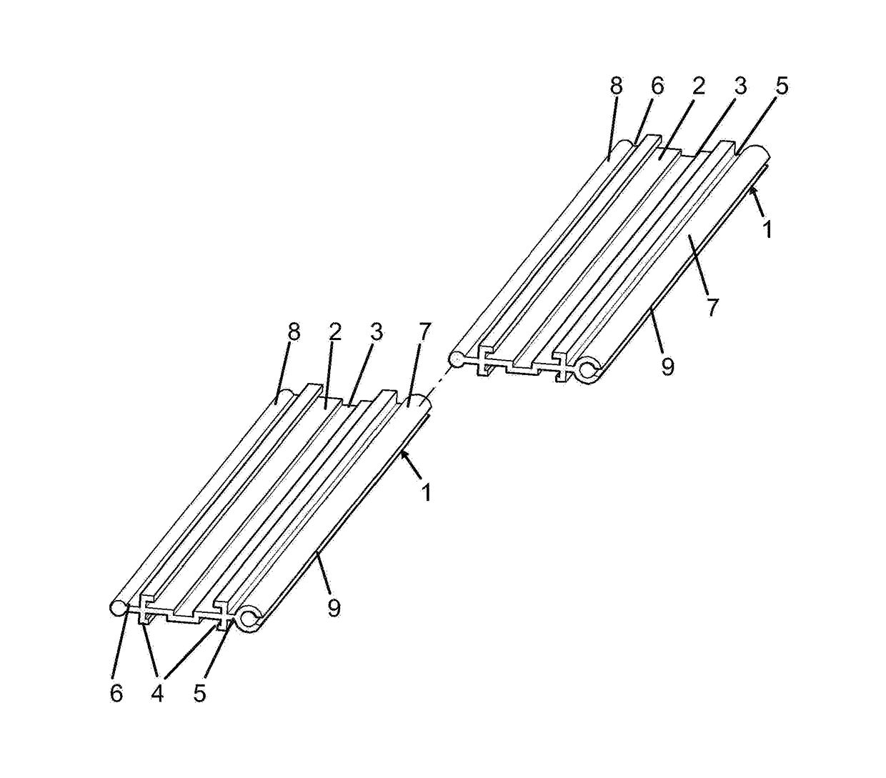
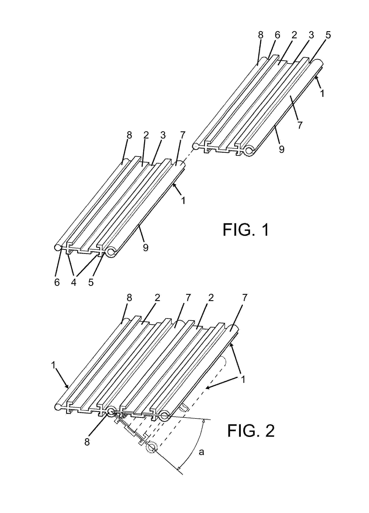
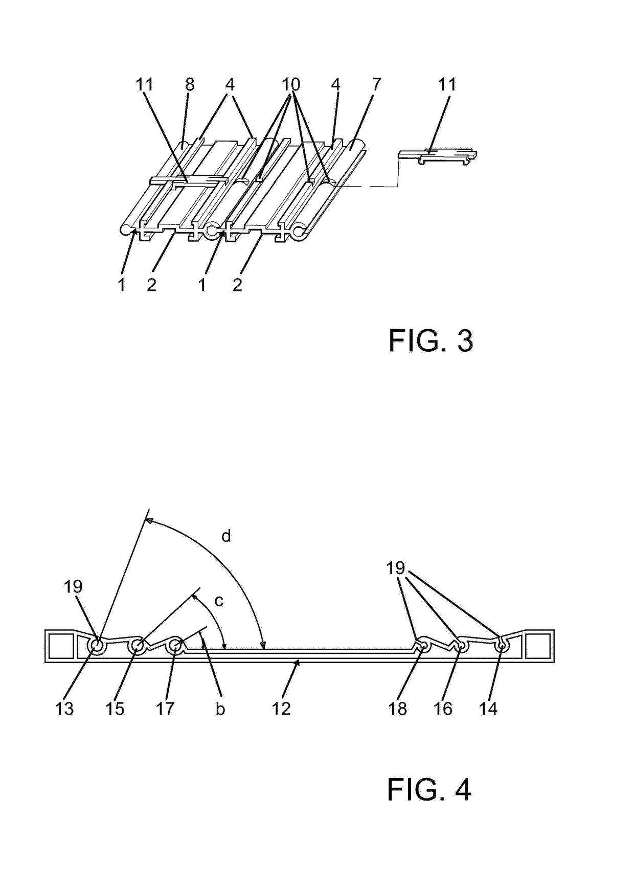
[0010]A pyrotechnic carrier structure that meets all the requisites mentioned above and that addresses the problems shown by conventional pyrotechnic structures is provided comprised of a firing base formed by multiple profiles arranged one alongside the other when the base is used. The pyrotechnic carrier structure comprises a base formed by at least one profile and preferably a plurality of profiles, of a number that can be increased depending on the needs of the user. The profiles can be manufactured, preferably made of aluminium or a different metal, extruded or laminated in conventional longitudinal bars, with profile widths arranged according to the needs of the user and cut at a workshop or at the place where they are fired, in predetermined lengths according to their use. The profiles have rails that extend longitudinally on at least one of their sides, typically the side opposite to the supporting surface, and a crosswise section modified to introduce the lateral extensions...


PUM


Abstract

The invention relates to a pyrotechnic carrier structure made from profiles (1) that can be interconnected on the edges thereof and with relative rotational freedom in order to form a firing base (20), to be horizontally arranged on the ground or warped for the arched arrangement thereof on support elements (12) formed by pairs of housings (13 and 14, 15 and 16, 17 and 18). Furthermore, the longitudinal movement of the profiles is avoided.

Description

SCOPE OF THE INVENTION[0001]The invention refers to a pyrotechnic carrier structure used for firing mortars containing fireworks.BACKGROUND OF THE INVENTION[0002]There are known pyrotechnic structures including firing bases formed by one or more pieces of thermoplastic material combined together and provided with housings that support the bases of the mortars containing the fireworks, so that they can be arranged at different angles. Typically, the housings are individual cavities open at the base and configured to receive the lower part of the pyrotechnic mortar. An example of this kind of firing bases is shown in document U.S. Pat. No. 5,429,053, in which an elongated body comprises a series of cavities that receive the bases of the mortars containing the fireworks. The support surface of the mortars is convex so that the mortars are placed at different angles.[0003]U.S. Pat. No. 4,222,306 describes a staggered arrangement of mortars that pursues the same goal. Naturally, only tub...

Claims


Application Information

Patent Timeline
Patent Type & Authority Applications(United States)
IPC IPC(8): F42B4/20F41A23/54
CPCF41A23/54F42B4/20
Inventor GARCIA GAMON, FERNANDOGARCIA GAMON, MANUELGARCIA-GAMON VALERO, ANTONIO MANUELGARCIA-GAMON ANTON, FERNANDOMARTINEZ JIMENEZ, JOSE MARIA
Owner GARCIA GAMON FERNANDO
Why Eureka
Try Eureka