Memory Migration Method and Device

a memory migration and memory technology, applied in the field of computer application technologies, can solve the problems of relatively large cpu usage, relatively low system performance, and relative large so as to improve cpu utilization, reduce a quantity of memory migration, and increase the performance cost of the system

Active Publication Date: 2017-03-09
HUAWEI TECH CO LTD
View PDF0 Cites 0 Cited by
  • Summary
  • Abstract
  • Description
  • Claims
  • Application Information

AI Technical Summary

Benefits of technology

[0017]It can be learnt from the foregoing description that, the embodiments of the present disclosure provide a memory migration method and device. The method includes receiving, by a first node, a migration instruction sent by a second node, sequentially scanning each memory page between a physical address of a start memory page accessed by a target process and a physical address of an end memory page accessed by the target process, where the memory page is a memory page accessed by the target process or a memory page accessed by a non-target process, combining a memory page that meets a block combination condition into a corresponding memory block, and migrating the corresponding memory block to a memory area of the second node, where the memory page that meets the block combination condition includes a memory page accessed by the target process or a memory page accessed by the non-target process. In this way, memory pages accessed by the target process and some memory pages that meet the block combination condition and that are accessed by the non-target process are combined into a corresponding memory block. Therefore, on the premise of not increasing performance costs of a system, discrete memory pages are combined together as many as possible for migration in a unit of memory block, which significantly reduces a quantity of memory migrations, and improves CPU utilization.

Problems solved by technology

In this case, if many memory pages need to be migrated, a relatively large quantity of migrations is caused.
As a result, CPU usage is relatively large, and system performance is relatively low.

Method used


Image

  • Memory Migration Method and Device
  • Memory Migration Method and Device
  • Memory Migration Method and Device

Examples


Embodiment Construction

[0024]The following clearly describes the technical solutions in the embodiments of the present disclosure with reference to the accompanying drawings in the embodiments of the present disclosure. The described embodiments are merely some but not all of the embodiments of the present disclosure. All other embodiments obtained by persons of ordinary skill in the art based on the embodiments of the present disclosure without creative efforts shall fall within the protection scope of the present disclosure.

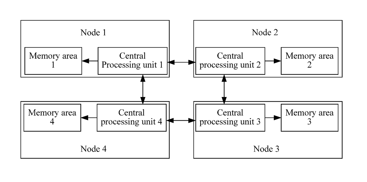
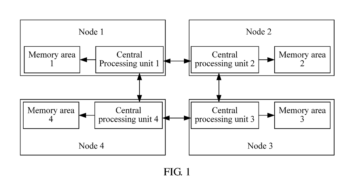
[0025]A memory migration method provided in an embodiment of the present disclosure is applicable to a NUMA system architecture shown in FIG. 1, and also applicable to memory migration in another communications scenario (for example, in a NUMA system or in a virtualization scenario), which are not limited in the present disclosure. In the present disclosure, only memory migration in the NUMA system architecture shown in FIG. 1 is used as an example for description.

[0026]In the NUMA s...


PUM


Abstract

A memory migration method and device relate to the field of computer application technologies. A memory page is combined into a memory block, which reduces a quantity of migrations, and improves central processing unit (CPU) utilization. The method includes receiving, by a first node, a migration instruction sent by a second node, sequentially scanning each memory page between a physical address of a start memory page accessed by a target process and a physical address of an end memory page accessed by the target process, where the memory page is a memory page accessed by the target process or a memory page accessed by a non-target process, determining whether each memory page meets a block combination condition, combining a memory page that meets the block combination condition into a corresponding memory block, and migrating the corresponding memory block to a memory area of the second node.

Description

CROSS-REFERENCE TO RELATED APPLICATIONS[0001]This application is a continuation of International Application No. PCT / CN2015 / 080491, filed on Jun. 1, 2015, which claims priority to Chinese Patent Application No. 201410464534.X, filed on Sep. 12, 2014. The disclosures of the aforementioned applications are hereby incorporated by reference in their entireties.TECHNICAL FIELD[0002]The present disclosure relates to the field of computer application technologies, and in particular, to a memory migration method and device.BACKGROUND[0003]A non-uniform memory access (NUMA) system architecture is one of server architectures. FIG. 1 is a schematic diagram of a NUMA system architecture. As shown in FIG. 1, the NUMA architecture includes multiple nodes, and each node includes one central processing unit (CPU) and a memory area corresponding to the CPU, where data in the memory area is stored using a memory page as a smallest unit. In the NUMA architecture, each CPU may access data in a local me...

Claims


Application Information

Patent Timeline
Patent Type & Authority Applications(United States)
IPC IPC(8): G06F3/06
CPCG06F3/0647G06F3/0619G06F3/064G06F3/0644G06F3/0683G06F12/06G06F12/0813G06F2212/2542G06F9/5016G06F9/5022G06F9/50G06F9/5033G06F3/06
Inventor CHU, LIXING
Owner HUAWEI TECH CO LTD
Why Eureka
Try Eureka