Rear mounted rotating mower assembly

Active Publication Date: 2017-03-16
DEERE & CO
View PDF2 Cites 4 Cited by
  • Summary
  • Abstract
  • Description
  • Claims
  • Application Information

AI Technical Summary

Benefits of technology

The patent is about a mower arm that can be pivoted to different positions. When the arm is in a third position, the machine has a feature that prevents the disc from spinning. The arm also has an electric motor that can rotate the discs in different patterns. The motor also adjusts the speed of the discs as the arm moves from the first to third position and from the third to second position. This allows for smoother operation and better control of the mower.

Problems solved by technology

Further, the location of the mower assembly is limited by the direction the discs are spinning as well as by the method of coupling the mower assembly to the output of the work machine.

Method used


Image

  • Rear mounted rotating mower assembly
  • Rear mounted rotating mower assembly
  • Rear mounted rotating mower assembly

Examples


Embodiment Construction

[0023]The embodiments of the present disclosure described below are not intended to be exhaustive or to limit the disclosure to the precise forms in the following detailed description. Rather, the embodiments are chosen and described so that others skilled in the art may appreciate and understand the principles and practices of the present disclosure.

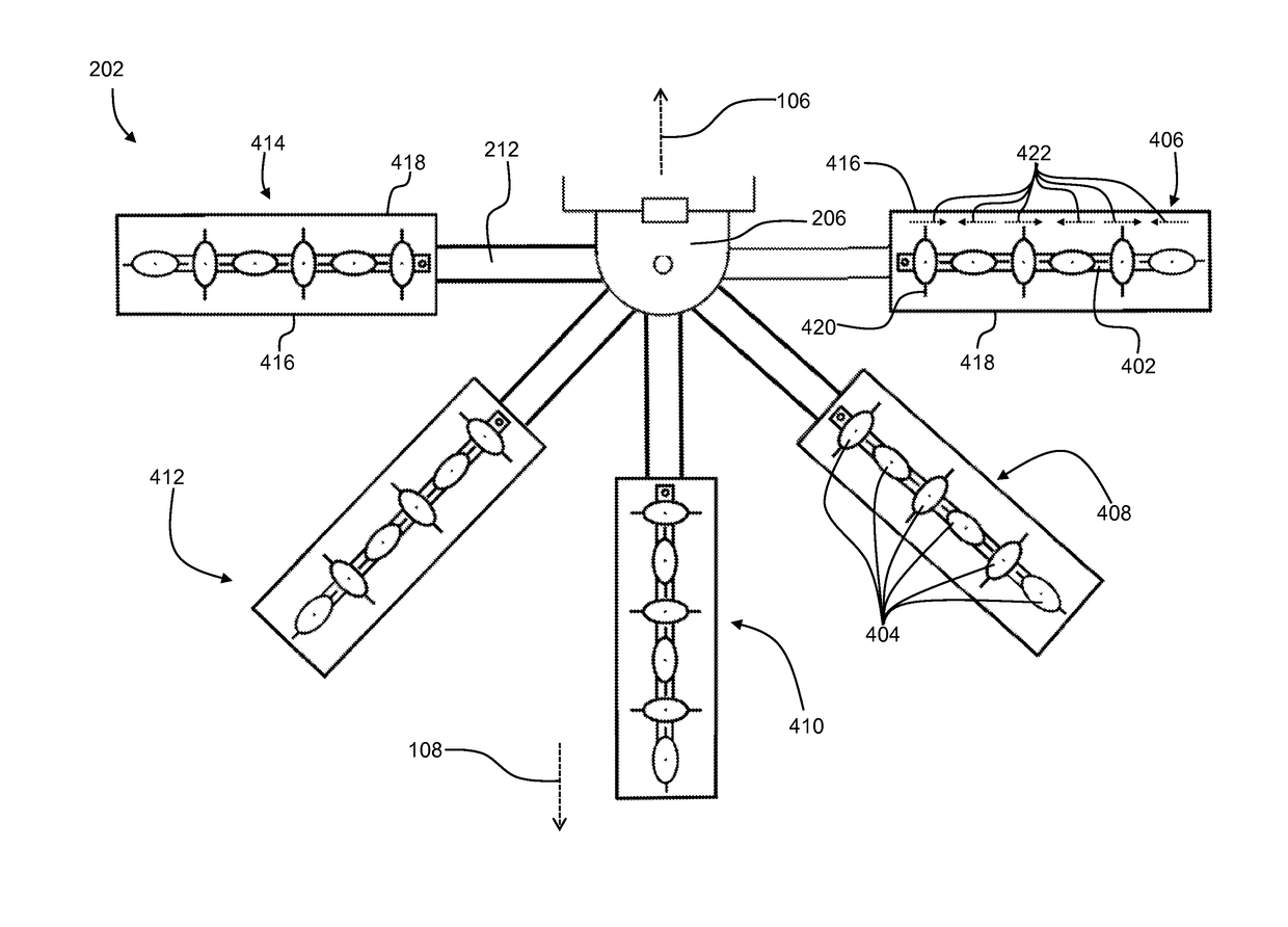
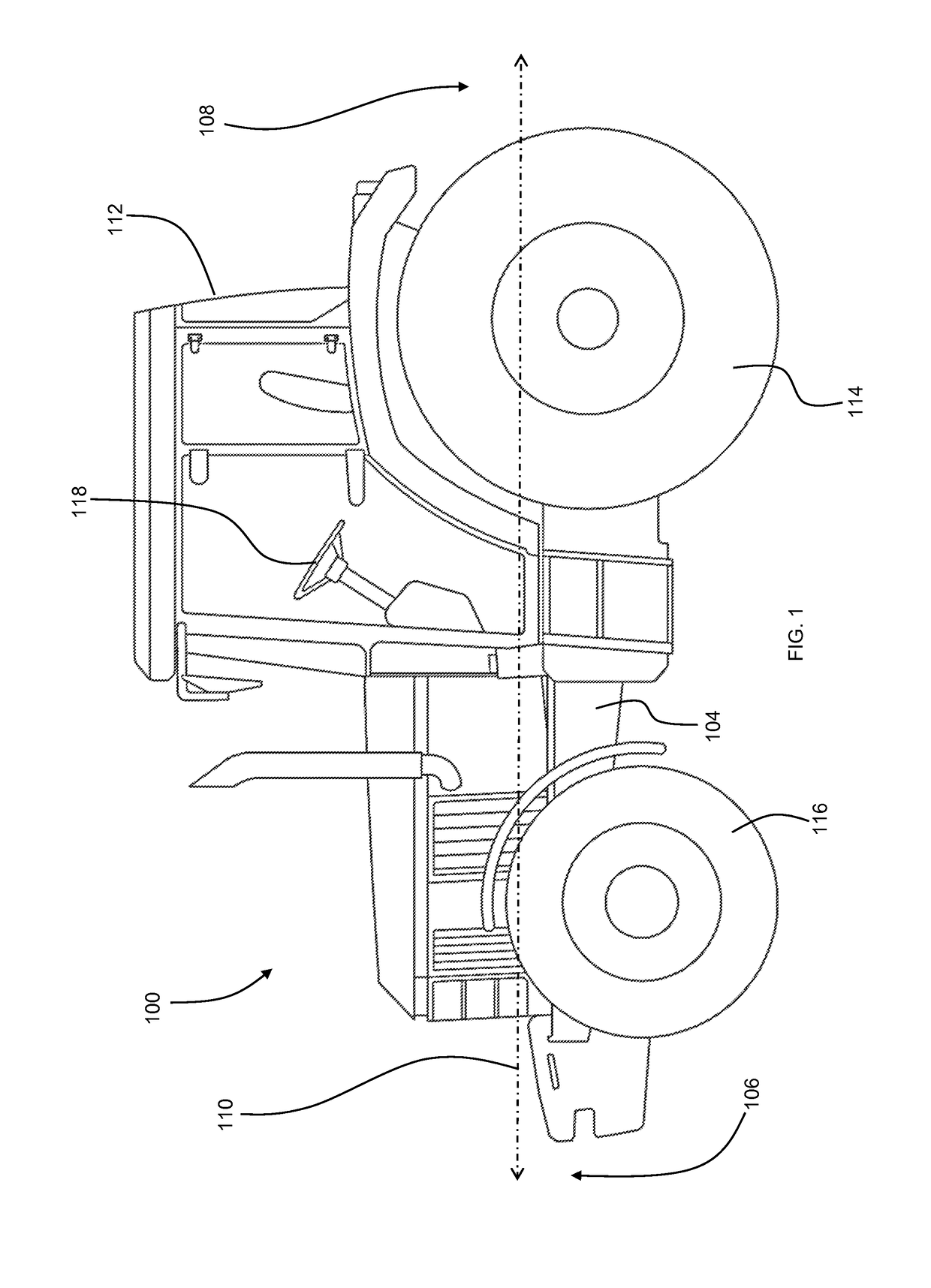
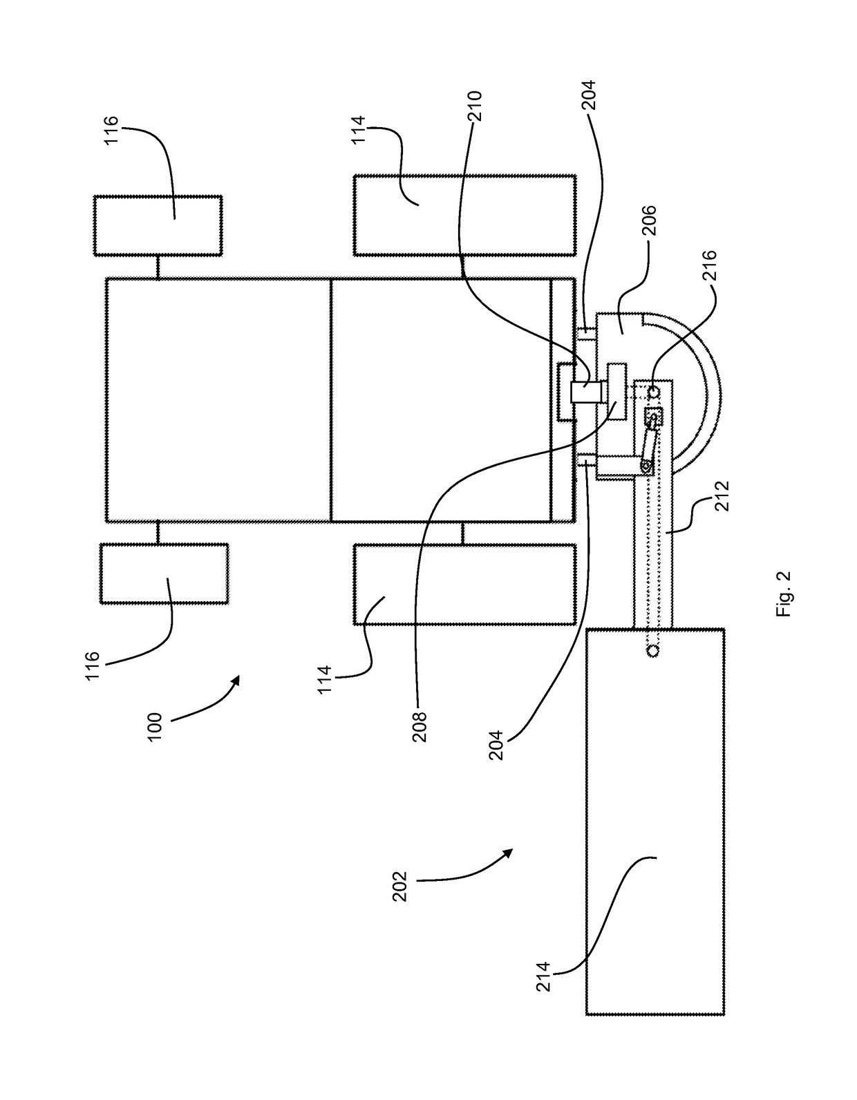
[0024]Referring to FIG. 1, a conventional tractor 100 is shown having a front 106 and a rear 108 disposed along a drive line axis 110. The tractor 100 may have controls 118 located in a cab 112. Further, the tractor 100 may travel along an underlying surface via one or more rear wheel 114 and one or more front wheel 116.

[0025]While a conventional tractor is shown, this disclosure is not limited to such a machine. Rather, the teaching of this disclosure may be applicable to any machine of any type of vehicle, work machine, or tractor that has a hitch assembly. More specifically, it is common for vehicles of many types to have a hitch sys...


PUM


Abstract

A mounted mower coupled to a hitch of a work machine that has an output, the mounted mower comprising a sub-frame having one or more hitch couplers selectively coupled to the hitch of the work machine. The mounted mower also has a mower arm with a first end and a second end, the first end being pivotally coupled to the sub-frame. The mower aim is pivotable about the first end between a first position and a second position relative to the sub-frame. The mower arm has a mower head mechanically coupled to the mower arm at the second end. The mower head has at least one disc pivotally coupled to the mower head, the at least one disc able to rotate about a disc pivot axis defined by the respective disc. Further, at least one disc may change the direction the disc rotates between the first and second position.

Description

FIELD OF THE DISCLOSURE[0001]The present disclosure relates to a tractor or other work machine with a rear mount hitch, and in particular, to a mower assembly that can be mounted to the rear mount hitch.BACKGROUND OF THE DISCLOSURE[0002]Work machines of many different types have rear mount hitch assemblies that provide a coupling location for a plurality of different implements or attachments. In addition to providing one or more coupling points, it is common for a rear mount hitch to provide an output for mechanical, electrical, or hydraulic power generated by an engine that also provides power to the work machine. Many implements or other attachments couple to the work machine through the coupling points and also mechanically, electrically, or hydraulically couple to the output to provide power to the implement. In one such configuration, a mowing assembly is coupled to the work machine.[0003]There are many different mowing assemblies that can be coupled to the rear mount hitch of...

Claims


Application Information

Patent Timeline
IPC IPC(8): A01D34/66A01D34/80A01D34/78A01D34/81A01D67/00
CPCA01D34/661A01D34/81A01D2101/00A01D34/78A01D34/80A01D67/005A01D34/76A01D34/866
Inventor EUBANKS, JASON C.
Owner DEERE & CO
Why Eureka
Try Eureka