Floating mobile water park

Active Publication Date: 2017-03-16
JOHNSON JR MICHAEL DAVID +1
View PDF2 Cites 4 Cited by
  • Summary
  • Abstract
  • Description
  • Claims
  • Application Information

AI Technical Summary

Benefits of technology

[0008]In view of the foregoing and other exemplary problems, drawbacks, and disadvantages of the conventional methods and structures, an exemplary fea

Problems solved by technology

As indicated above, conventional floating water

Method used


Image

  • Floating mobile water park
  • Floating mobile water park
  • Floating mobile water park

Examples


Example

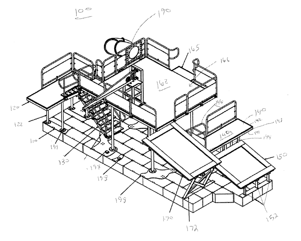
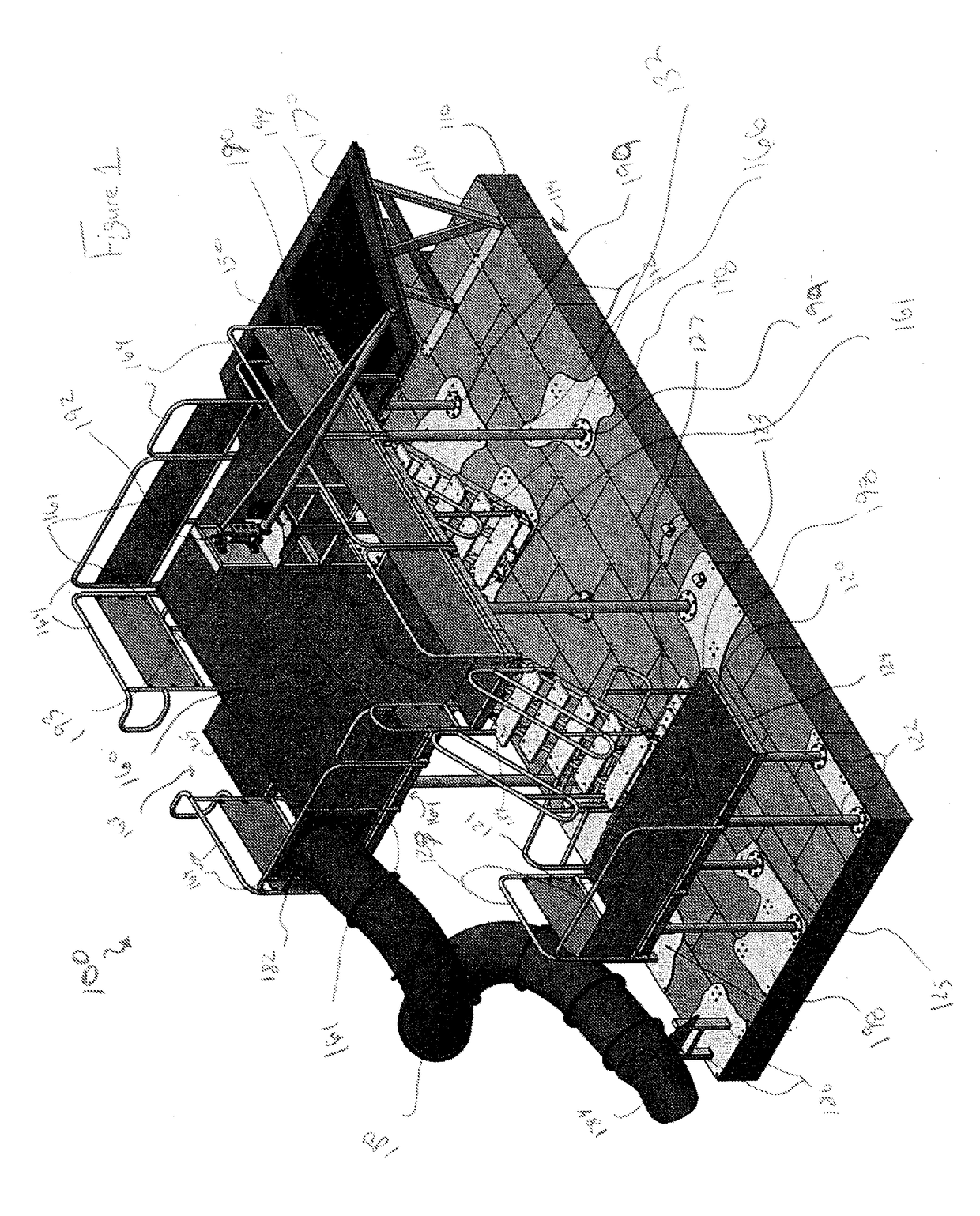
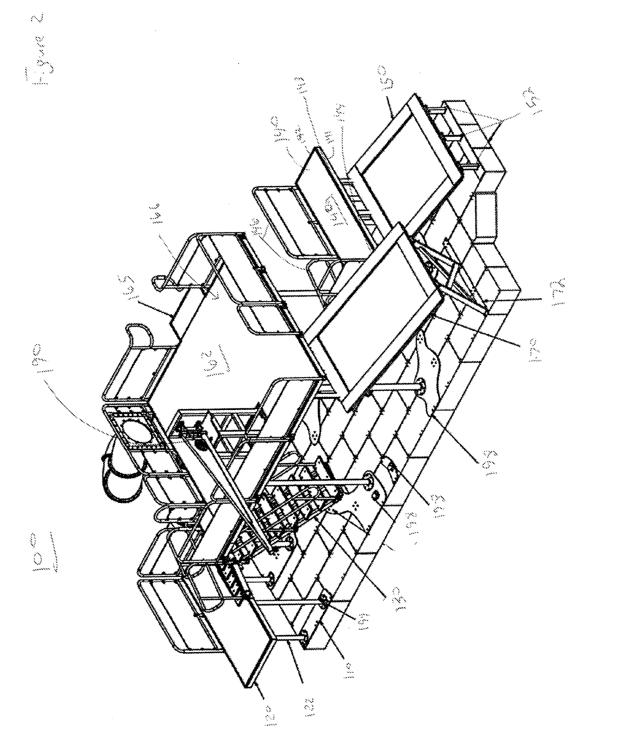
[0022]Referring now to the drawings, and more particularly to FIGS. 1-6, there are shown exemplary embodiments of the present invention.

[0023]FIGS. 1-3 illustrate a floating amusement apparatus 100 according to a first exemplary embodiment of the present invention. Each of FIGS. 1-3 illustrates the floating apparatus 100 from varying perspective views. The floating amusement apparatus 100 includes a base 110. The base 110 is made of a modular floating dock. The modular floating docket is constructed from a plurality of individual modules 112. The plurality of individual modules 112 form the hull of the apparatus 110 having a flat top surface 116 and a flat bottom surface 114. The modular floating dock base 110 advantageously provides a stable base, the top surface 116 of which is able to remain close to water level when the apparatus 100 is in use. All other components of the floating amusement apparatus 100 are mounted to the base 110, directly or indirectly. The floating modular d...


PUM


Abstract

A floating amusement apparatus includes a base, at least one elevated platform secured to and supported above the base and a plurality of user-interactive amusement accessories secured to the base or the at least one elevated platform. The base includes a modular floating dock. The floating amusement apparatus is adapted to be mobile.

Description

CROSS REFERENCE TO RELATED APPLICATIONS[0001]This present application claims priority to U.S. Provisional Application No. 62 / 216,873, which was filed on Sep. 10, 2015, which is herein incorporated by reference.BACKGROUND OF THE INVENTION[0002]Field of the Invention[0003]The present invention relates to amusement rides and more particularly to a water amusement assembly and more specifically to a stable, mobile, floating amusement apparatus.[0004]Description of the Background Art[0005]In hot summer weather, it is common to undertake water-based amusement activities. For example, swimming pools, oceans and lakes are typically enjoyed on hot weather days. Often it is desirable to use water-based amusement features such as rope swings, diving boards, water slides, etc. Often these amusement features can be found at a specific location, such as a water park. It is sometimes desirable, however, to have such amusement features at a personal location. For example, inflatable water slides ar...

Claims


Application Information

Patent Timeline
IPC IPC(8): A63G31/00A63B5/10A63G9/00A63B5/11A63G21/02
CPCA63G31/007A63B5/11A63B5/10A63G9/00A63G21/02A63B2225/605A63G31/00
Inventor JOHNSON, JR., MICHAEL DAVIDHAMPTON, CHRISTOPHER NELSON
Owner JOHNSON JR MICHAEL DAVID
Why Eureka
Try Eureka