Transponder system for localization of an object

a transponder system and object technology, applied in the field of transponder system for localization of objects, can solve the problems of not being suitable for larger transports of valuable objects, not being suitable for other individual objects of value, and not being easy to locate objects

Inactive Publication Date: 2001-05-22
WESTMAN TONY +1
View PDF11 Cites 95 Cited by
  • Summary
  • Abstract
  • Description
  • Claims
  • Application Information

AI Technical Summary

Problems solved by technology

Today a frequent problem consists in thefts whereby there is no simple way to easily locate these objects.
These systems are however not suitable for larger transports of valuables, nor are they suitable for other individual objects of value.
A limited amount of control information may be transferred to the transponder which however is not applicable for portable use.
This system like the previously discussed is also not intended to be portable.
Sensors for d

Method used


Image

  • Transponder system for localization of an object
  • Transponder system for localization of an object
  • Transponder system for localization of an object

Examples


application examples

EMBODYING APPLICATION EXAMPLES

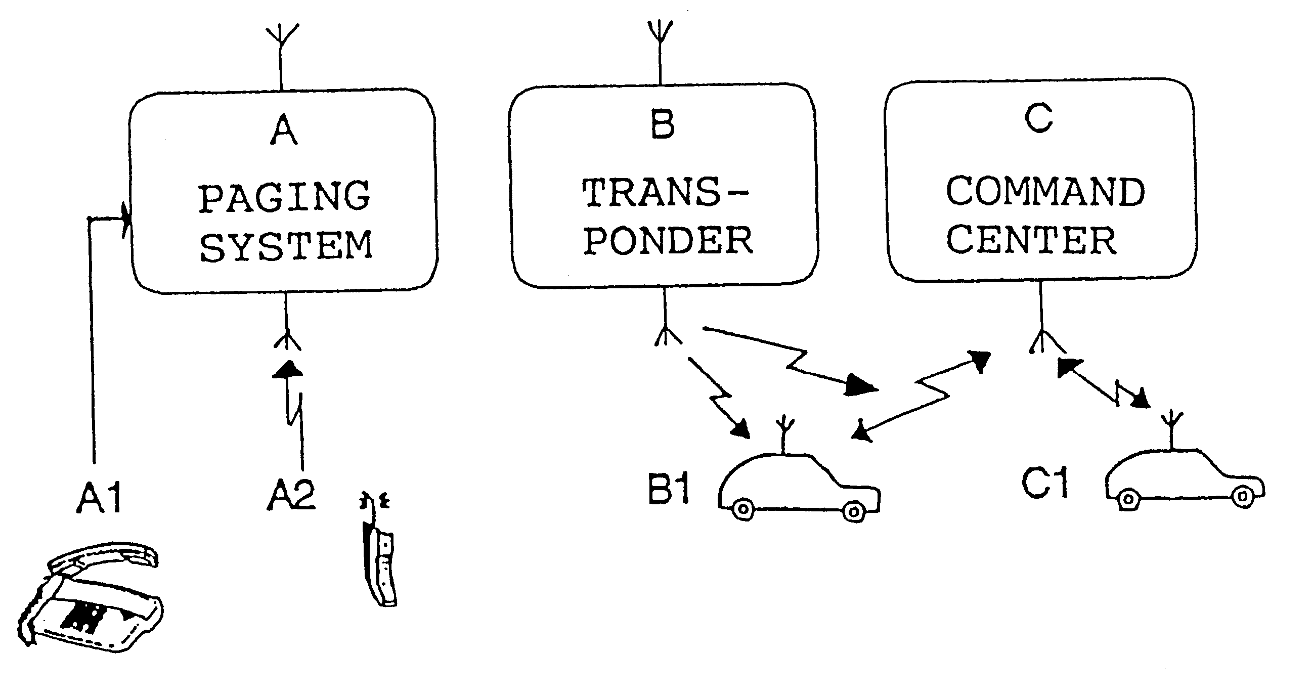
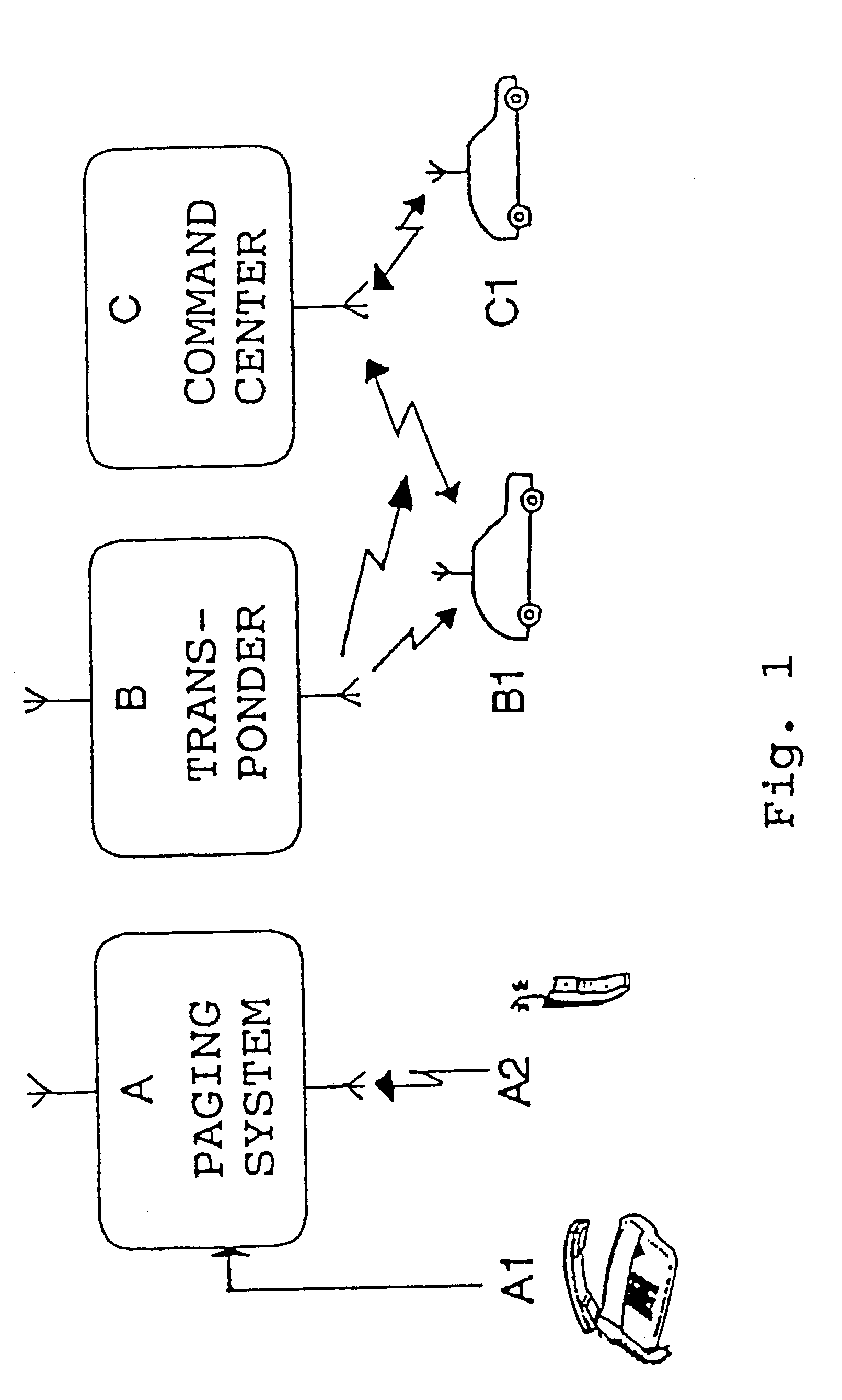
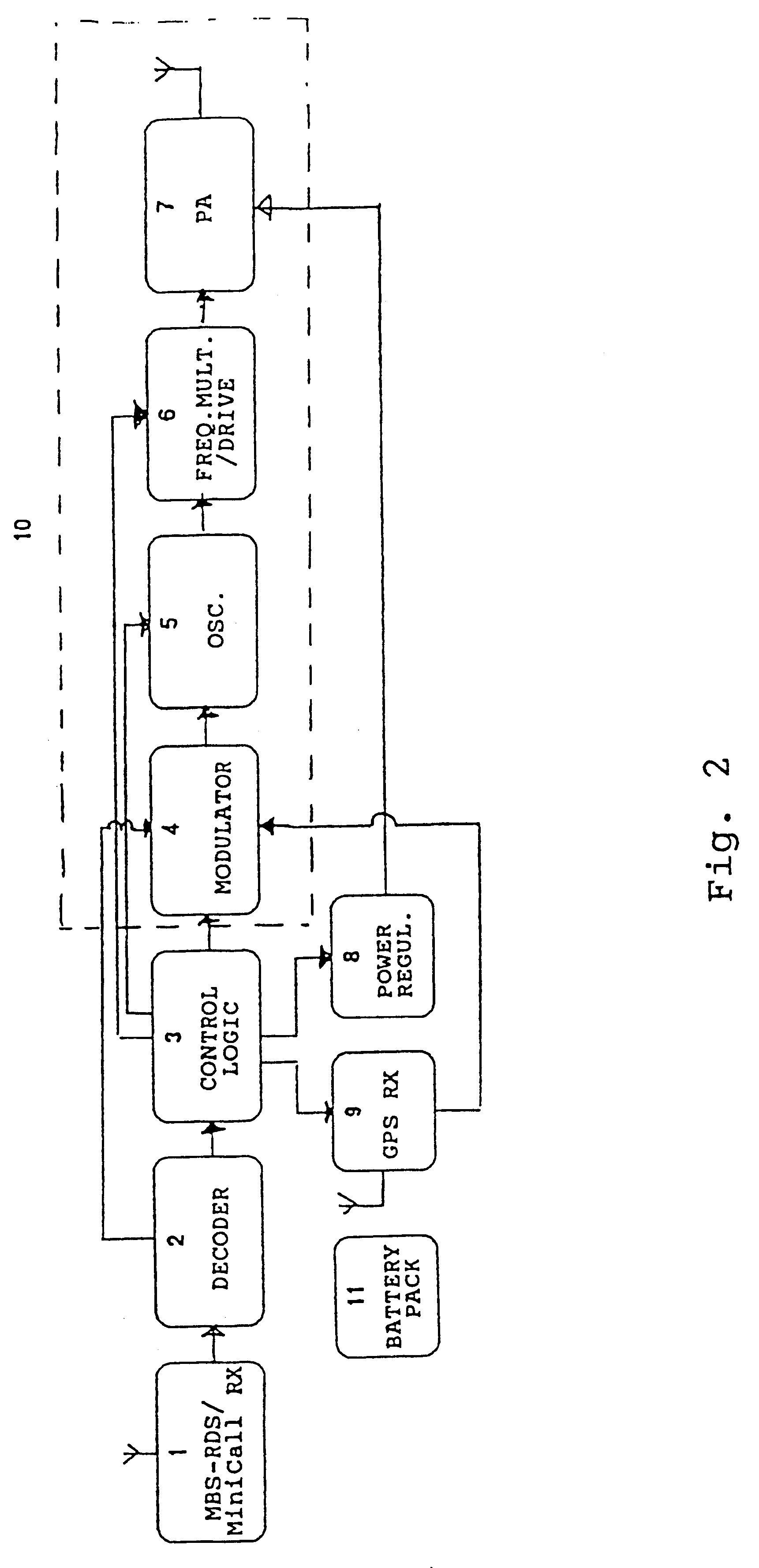
In for example the tracking of valuable transport goods one or several transponders are placed together with the valuable goods, e.g., in a bag for money. Such small transponders are easily located with the valuable goods by, e.g., banking staff. The transponder B or the transponders at this occasion is / are in standby, i.e., it or they will not be transmitting any information and the power consumption consequently will be very small as only the receiver 1 for MBS-RDS / MiniCall needs to be in its receiving state.

third embodiment

Upon theft of the valuable transport goods enabling is automatically performed in a third embodiment according to the present invention if the valuable goods containing the transponder is put outside a defined surveillance area. Enabling of for example the transponder B will occur when a signal coming from a given surveillance transmitter, preferably around 170 MHz (MiniCall), is not repeatedly received within a predetermined time period.

In all embodiments it is additionally possible to, via the paging network, enable the respective transponder B manually by means of a stationary or mobile telephone, A1 and B1, respectively, dialing its unique phone number and additionally then give the unique authorization code of the transponder. If only the authorization code of the transponder is given without control code, which is equal to that the control code being equal to "0", the transponder B will transmit its identity with a certain predetermined repetition frequency having interval and...

second embodiment

The utilized technique further means that all control codes being sent to the transponder B over the paging system and not having the control bit 1 set, will accordingly always enable the transponder, why for the different embodiments it is sufficient to send the authorization code in order to enable the transponder. This principle somewhat modified is for example also utilized in the previously mentioned second embodiment where the transponder B senses a transmitter within a surveillance area. If this transmitter does not within a certain time period transmit a signal to keep control bit 1 set, the transponder is automatically enabled by theft of the object when it is taken beyond the range of the surveillance transmitter. This is done according to conventional technique in that the control logic is having a time function which after a predetermined time period sets this control bit 1 to "0" if the signal from the surveillance transmitter is not detected.


PUM


Abstract

A transponder system is provided which presents a light weight portable or mobile system for localization of movable objects, e.g., for surveillance of valuable transports and the like. The small unit constituting the transponder contains a receiver (1) of paging type, a decoder (2), a logic unit (3), a transmitter portion (10), a built-in antenna and power supply (11). The system is controllable by an existing tested radio system for paging. One advantage of utilizing an already existing paging system is that functionality is well tested and a general covering range is obtained. In addition, costs for building up and operation of a paging system are eliminated. Control information being sent to the transponder includes a number of symbols defining a certain basic function for the built-in marker transmitter (10) and symbols which constitute control code and control data for the specific function. Consequently at least the frequency, transmit power and transmitting sequences of the marker transmitter are controllable.

Description

The present invention relates to a portable / mobile transponder for the localizing of movable objects and more exactly the transponder according to the present invention is possible to be enabled via an existing radio network, e.g. type MiniCall and / or MBS-RDS.PRIOR ARTToday a frequent problem consists in thefts whereby there is no simple way to easily locate these objects. In certain cases, e.g., in the transportation of valuables, cassettes are used which contain a system such that if the cassette is unauthorizedly opened a device is triggered for example staining the banknotes. These systems are however not suitable for larger transports of valuables, nor are they suitable for other individual objects of value.Therefore in the surveillance of objects which are easily being moved there exists a general demand for a marker transmitter, which for example, is possible to enable if the object to be guarded is brought out of a surveillance area. Such a marker or transponder then must be...

Claims


Application Information

Patent Timeline
IPC IPC(8): G01S13/00G01S13/82G01S5/14G01S13/74
CPCG01S13/825
Inventor WESTMAN, TONYNARHI, ANNE
Owner WESTMAN TONY
Why Eureka
Try Eureka