Glass

a technology of glass and shards, applied in the field of glass, can solve the problems of double images, pose problems for the driver of a vehicle, and double images in perspective may also pose problems

Active Publication Date: 2017-03-16
ASAHI GLASS CO LTD
View PDF6 Cites 23 Cited by
  • Summary
  • Abstract
  • Description
  • Claims
  • Application Information

AI Technical Summary

Benefits of technology

[0014]According to an embodiment in the present disclosure, it is possible to provide glass with which perspective distortion generated at the boundary between the HUD-display area and the non-HUD-display area can be reduced.

Problems solved by technology

However, there may be cases where double images pose a problem when the driver is visually recognizing an outside scene or information displayed by the HUD.
There are two types of double images that pose problems for the driver of a vehicle.
Therefore, if the windshield has an HUD-display area used by the HUD, and a non-HUD-display area (a transparent area) not used by the HUD, the main problem posed in the HUD-display area is reflective double images although perspective double images may also pose a problem, and the problem posed in the non-HUD-display area is perspective double images.
However, if the wedge angle is steeply changed in a certain area in the glass, a problem arises in that perspective distortion is generated in the steeply changed area (transitioning area).

Method used


Image

  • Glass
  • Glass
  • Glass

Examples


application example 1

Description of Application Example 1 and Comparative Examples 1 to 4

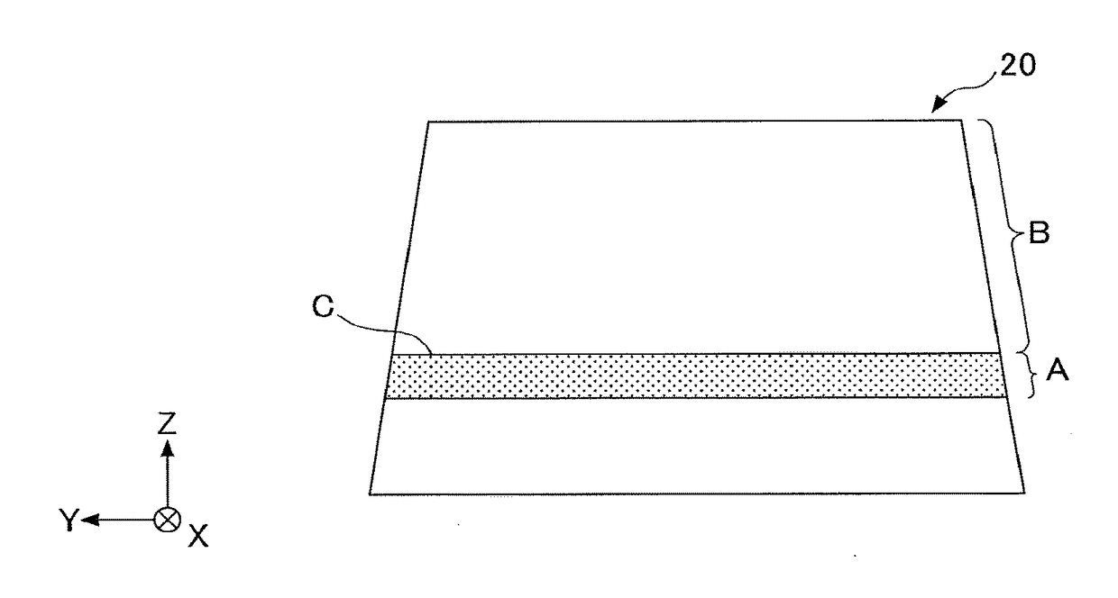
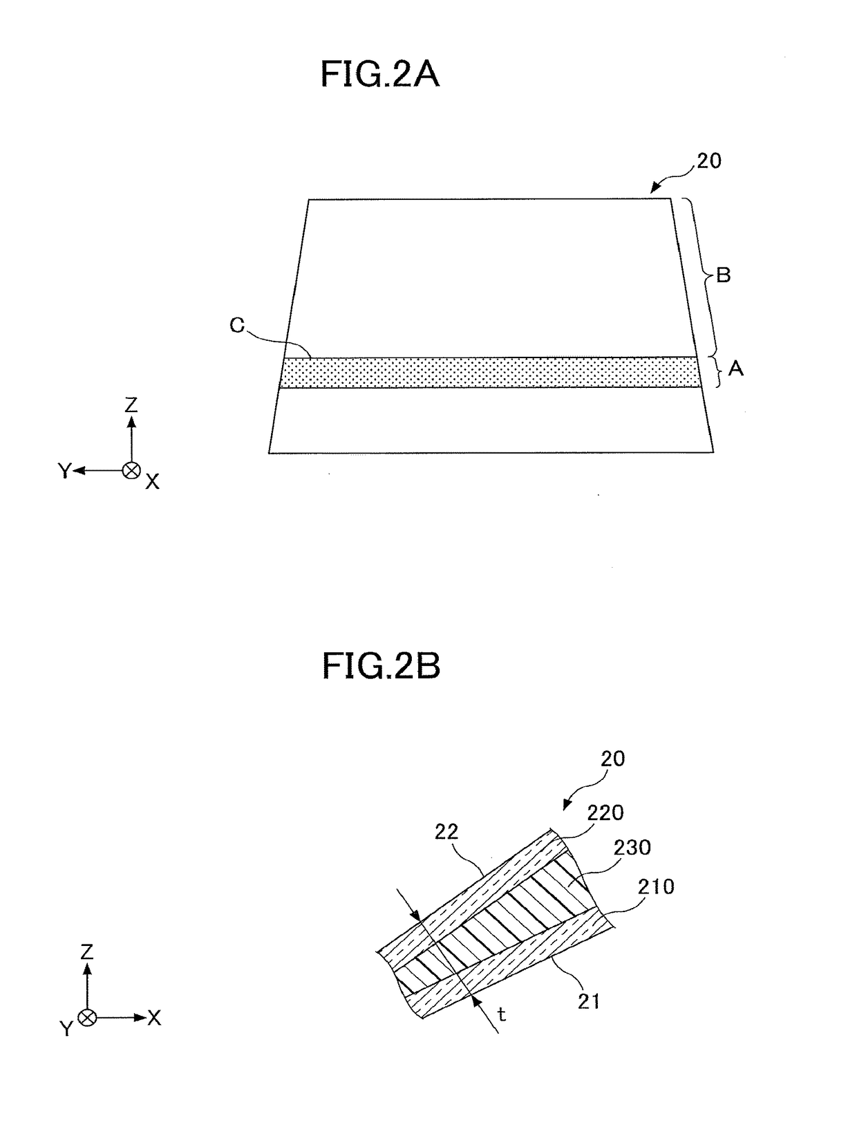
[0050]First, comparative examples 1 to 4 will be described. The comparative example 1 is a case in which both the wedge angle δ in the HUD-display area A and the wedge angle δ in the non-HUD-display area B are zero mrad (the inner surface 21 and the outer surface 22 of the windshield 20 are always parallel to each other in the HUD-display area A and the non-HUD-display area B). The comparative example 2 is a case in which both the wedge angle δ in the HUD-display area A and the wedge angle δ in the non-HUD-display area B are 0.7 mrad. The comparative example 3 is a case in which the wedge angle δ in the HUD-display area A is 0.7 mrad, and the wedge angle δ in the non-HUD-display area B is zero mrad.

[0051]The comparative example 4 is a case that is described in Patent Document 1. In other words, that is the case in which the wedge angle δ in the HUD-display area A is determined based on the following Formulas (5), (6...

application example 2

[0068]In the application example 1, the example has been described in which Formula (1) is applied to the entire area of the non-HUD-display area B that includes the edge on the boundary C side in the non-HUD-display area B. However, Formula (1) has an object to prevent change of the wedge angle at the boundary C, and hence, may not be necessarily applied to the entire area of the non-HUD-display area B. Thereupon, in the application example 2, an example will be described in which Formula (1) is applied only to a partial area of the non-HUD-display area B that includes the edge on the boundary C side in the non-HUD-display area B. Other matters are the same as in the application example 1 unless specifically described.

[0069]FIG. 8 illustrates change of the wedge angle in the X-direction where the HUD-display area A is set in the range of 400 mm≦X1 and B2. Further, Formula (1) is applied to the area B1 of the non-HUD-display area B that is adjacent to the boundary C. Note that the s...


PUM

PropertyMeasurementUnit
wedge angleaaaaaaaaaa

Abstract

Glass having an inner surface and an outer surface, includes a first area used by a head-up display, and a second area adjacent to the first area, and not used by the head-up display. Representing an area closest to a boundary between the first area and the second area in the first area, by an edge on the boundary side in the first area, and representing an area closest to the boundary in the second area, by an edge on the boundary side in the second area, a requirement is that a wedge angle δ formed by the inner surface and the outer surface satisfies a predetermined formula.

Description

CROSS-REFERENCE TO RELATED APPLICATION[0001]The present application is a continuation application filed under 35 U.S.C. 111(a) claiming benefit under 35 U.S.C. 120 and 365(c) of PCT International Application No. PCT / JP2015 / 071199 filed on Jul. 27, 2015 and designating the U.S., which claims priority of Japanese Patent Application No. 2014-155188 filed on Jul. 30, 2014, and Japanese Patent Application No. 2015-087068 filed on Apr. 21, 2015. The entire contents of the foregoing applications are incorporated herein by reference.BACKGROUND OF THE INVENTION[0002]1. Field of the Invention[0003]The present disclosure relates to glass.[0004]2. Description of the Related Art[0005]In recent years, introduction of head-up displays (referred to as “HUD”, below) has made progress, with which predetermined information is displayed in the field of vision of the driver of a vehicle, by reflecting images on the windshield of the vehicle. However, there may be cases where double images pose a problem...

Claims


Application Information

Patent Timeline
Patent Type & Authority Applications(United States)
IPC IPC(8): B32B17/10
CPCB32B17/10568B32B2605/006B32B17/10036G02B27/0101G02B2027/0121
Inventor SADAKANE, SHUNSUKENODA, KAZUYOSHI
Owner ASAHI GLASS CO LTD
Why Eureka
Try Eureka