

Multi-fuel engine controls including multi-factor cost optimization
a multi-fuel engine and cost optimization technology, applied in the direction of electric control, machines/engines, mechanical equipment, etc., can solve the problems of existing attempts to provide controls for multi-fuel engines
- Summary
- Abstract
- Description
- Claims
- Application Information
AI Technical Summary
Benefits of technology
Problems solved by technology
Method used
Image

Examples
Embodiment Construction
[0002]For the purposes of clearly and concisely summarizing and describing exemplary embodiments of the invention, the manner and process of making and using the same, and to enable the practice, making and use of the same, reference will now be made to certain exemplary embodiments, including those illustrated in the figures, and specific language will be used to describe the same. It shall nevertheless be understood that no limitation of the scope of the invention is thereby created, and that the invention includes and protects such alterations, modifications, and further applications of the exemplary embodiments as would occur to one skilled in the art.
SUMMARY OF THE DISCLOSURE
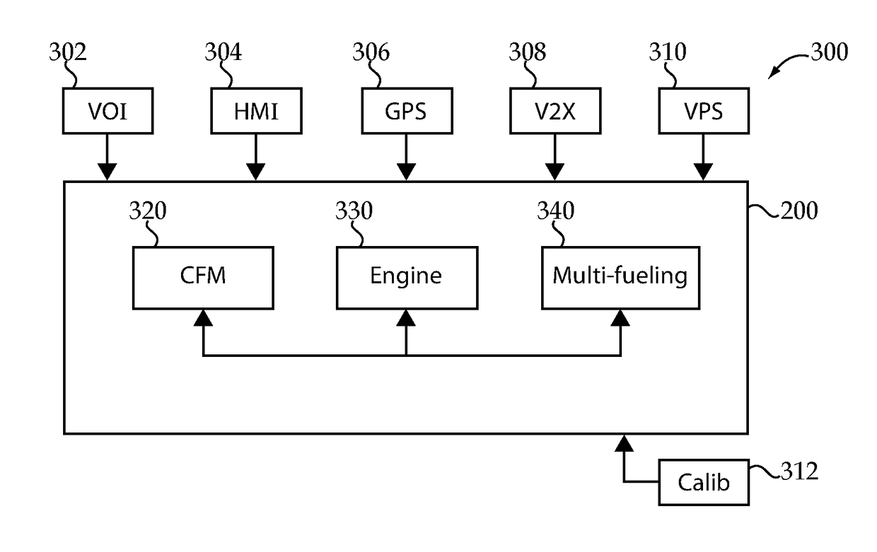
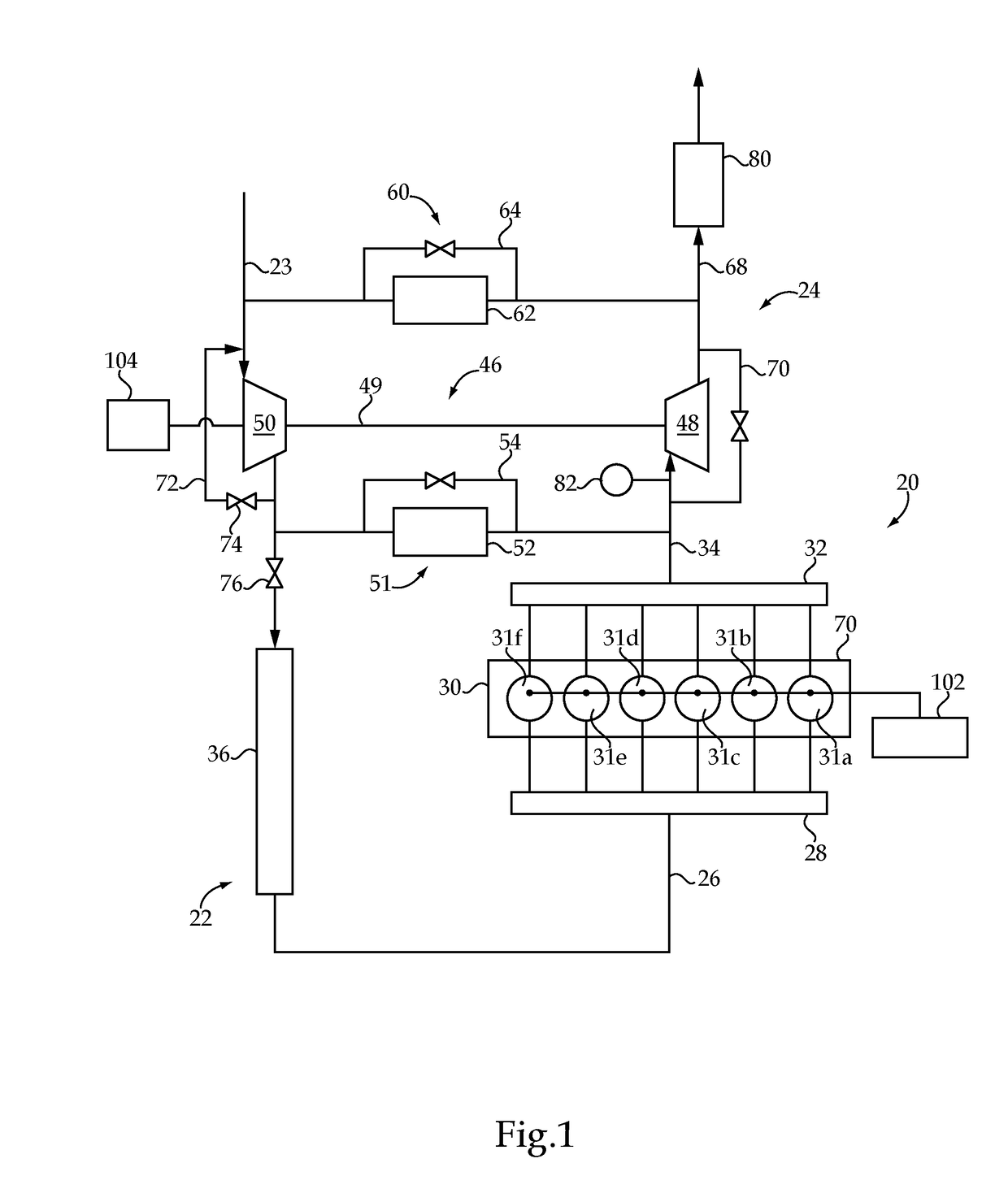
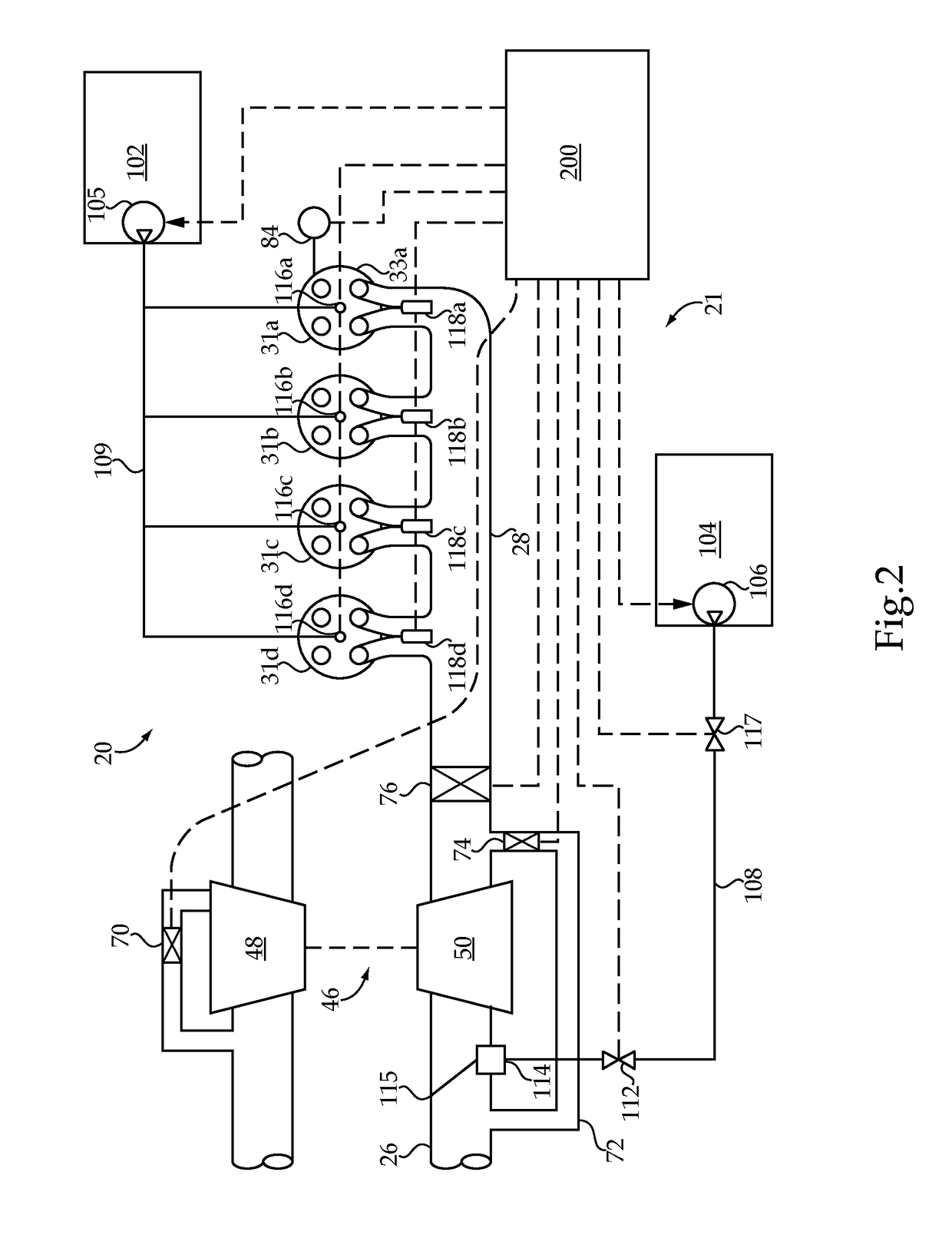
[0003]Unique multi-fuel engine controls and apparatuses, methods and systems relating to the same are disclosed. One exemplary embodiment is a system comprising a multi-fuel engine structured to selectably combust varying proportions of a first type of fuel and a second type of fuel, and an electronic contr...
PUM
 Abstract
Description
Claims
Application Information