Hydromechanical transmission electronic control system for high speed vehicles

a transmission electronic control and high-speed vehicle technology, applied in the direction of fluid couplings, gearings, instruments, etc., can solve the problems of difficult inability to react quickly to a dynamic operating environment, and hmts often have difficulty in quick reaction, etc., to achieve smooth startup conditions.

Inactive Publication Date: 2005-04-21
DANFOSS POWER SOLUTIONS INC
View PDF6 Cites 82 Cited by
  • Summary
  • Abstract
  • Description
  • Claims
  • Application Information

AI Technical Summary

Benefits of technology

[0012] Because of the present invention's ability to provide a smooth startup condition, the present invention is best suited for use with dynamic operating conditions. In particular, the present invention reacts quickly to rapidly changing load and operation characteristics. Further, the present invention is best suited for use with high speed vehicles. The invention is intended for use with ATVs; however, the present invention also may be used with other types of vehicles, both large and small.
[0013] The present invention is optimized for ratio-controlled HMTs. In such an arrangement, the transmission constantly connects the engine to the load, and the transmission ratio is only varied by a change in command from the electronic control system. The transmission's mechanical function is solely to vary the ratio between its input and output. This is different from conventional transmissions, which use a torque or load-sensitive device, such as a slipping belt, centrifugal clutch, pressure-modulated clutch, or torque converter, to achieve a smooth startup condition.

Problems solved by technology

Smooth startup conditions, however, are difficult to achieve with HMTs.
Another disadvantage of HMTs is the inability to react quickly to a dynamic operating environment.
HMTs often have difficulty reacting quickly to these factors, producing a harsher ride than conventional belt-driven units.
Yet another disadvantage of HMTs is the inability to react to operator-controlled braking systems.
HMTs typically provide very little dynamic braking capability and therefore must be protected from overspeed during vehicle deceleration.

Method used


Image

  • Hydromechanical transmission electronic control system for high speed vehicles
  • Hydromechanical transmission electronic control system for high speed vehicles
  • Hydromechanical transmission electronic control system for high speed vehicles

Examples


Embodiment Construction

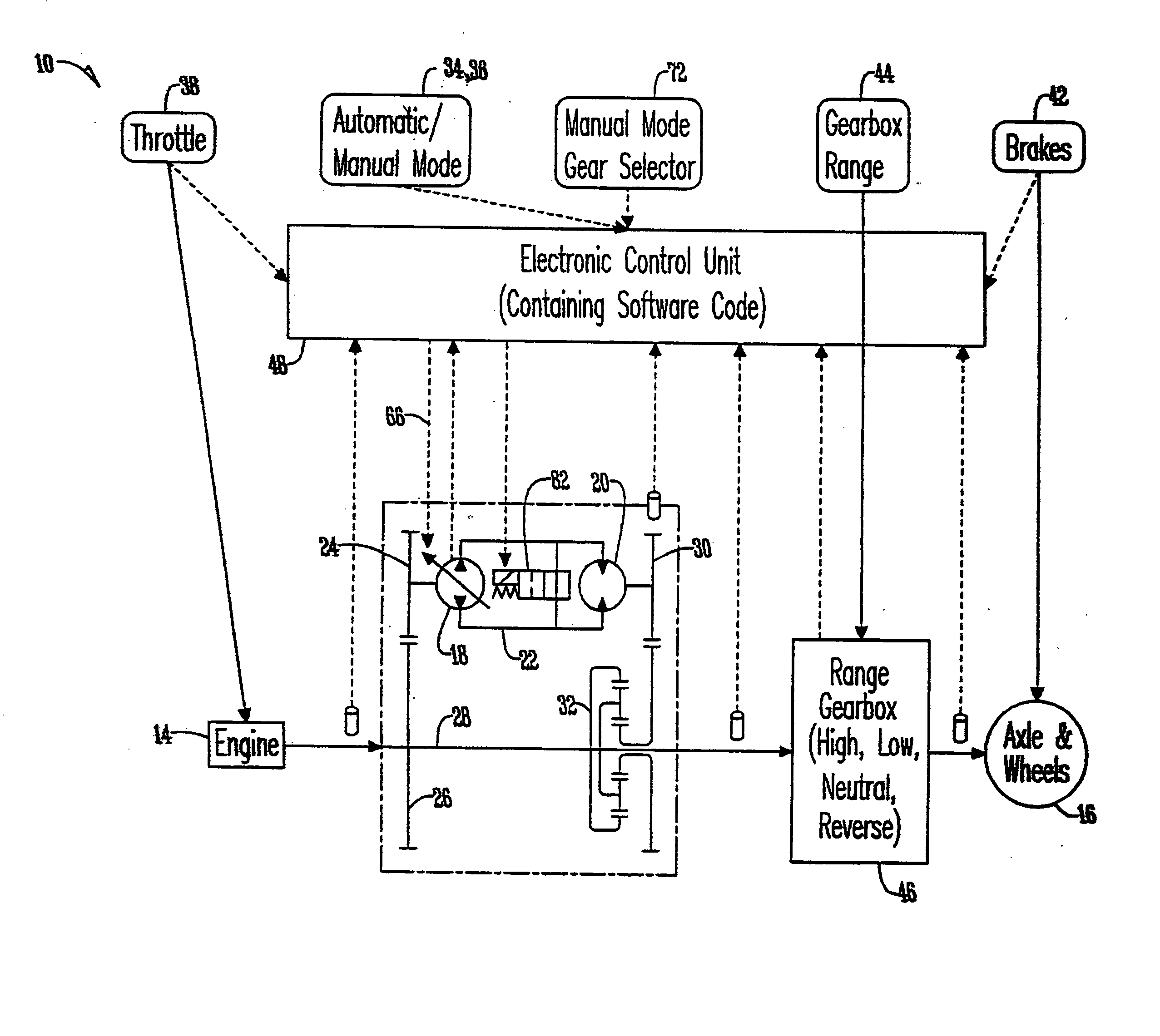
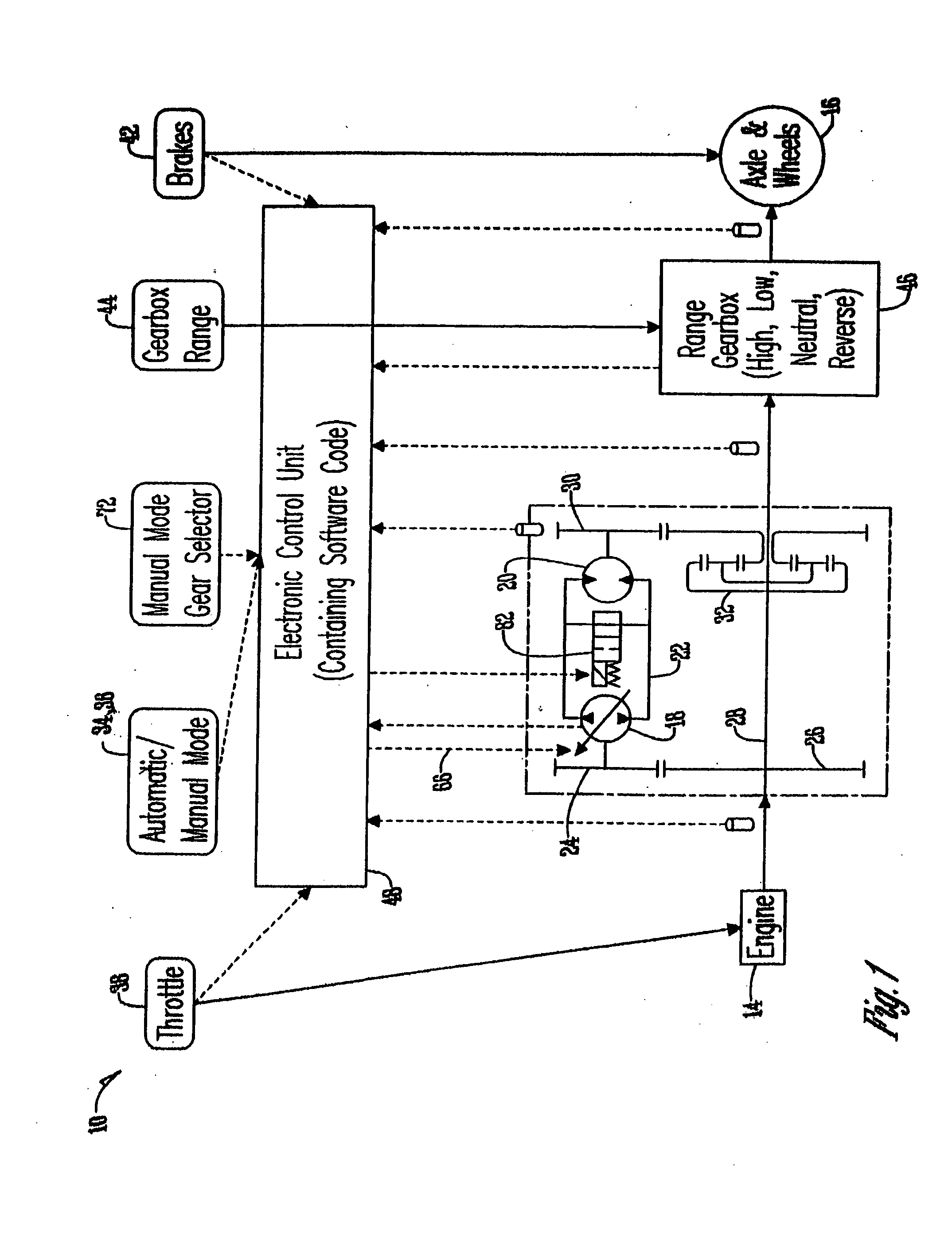
[0020] With respect to FIG. 1, an electronic transmission control system 10 is disclosed that achieves a transmission ratio based on the operator inputs and the current vehicle operating conditions. The electronic transmission control system 10 works to control HMT 12, which connects a vehicle engine 14 to the vehicle wheels 16.

[0021] HMT 12 includes a pump 18 connected to a motor 20 by closed loop 22. Pump 18 is connected to a driven gear 24 rotated by driving gear 26, which is connected to a crank shaft 28. Motor 20 is connected to gear 30, which is connected to planetary gear set 32 and works to drive wheels 16.

[0022] A glossary of terms for use in describing the control system 10 appears below:

TermDescriptionAutomatic ModeElectronic control systemautomatically sets transmissionratio.Brake CommandSensed position of operator'sbrake commanded (typically alever or pedal).Commanded Engine SpeedThrottle position that has beenconverted to RPMs. This is anapproximate curve based on ...


PUM


Abstract

An electronic transmission control system is provided that can achieve a transmission ratio based on the operator inputs and the current vehicle operating conditions. The transmission constantly connects the engine to the load, and the transmission ratio is only varied by a change in command from the present invention. The transmission's mechanical function is solely to vary the ratio between its input and output. In using the present invention, an operator must select an operating mode, either automatic or manual, using a two-position switch. While in the automatic mode, the present invention determines the vehicle speed by considering the position of the throttle and the operator's use of brakes. In the manual mode, the present invention further considers the operator's selection of a gear condition.

Description

CROSS REFERENCE TO A RELATED APPLICATION [0001] This application is based upon Applicants' Provisional Application Ser. No. 60 / 396,653 filed Jul. 18, 2002.BACKGROUND OF THE INVENTION [0002] This invention relates generally to hydromechanical transmissions and, more particularly, to electronic control systems for hydromechanical transmissions. [0003] Hydromechanical transmissions (HMTs) have been developed for vehicles to replace conventional automatic belt drive transmissions. In particular, HMTs have been developed for use with all-terrain vehicles (ATVs). The advantages of HMTs include increased power capacity, greater durability, and protection from environmental degradation. Even though the mechanical implementation and functionality of HMTs is very different from conventional belt-driven units, consumers prefer that vehicles drive and feel like conventional belt-driven units while still offering the advantages of HMTs. [0004] Conventional belt drive transmissions use a centrifu...

Claims


Application Information

Patent Timeline
Patent Type & Authority Applications(United States)
IPC IPC(8): B60K31/00F16H47/04F16H59/24F16H59/44F16H59/54F16H59/68F16H61/40F16H61/4043F16H61/42F16H61/46F16H61/462
CPCB60W2510/0604Y10T477/631B60W2520/10B60W2540/12F16H47/04F16H59/24F16H59/44F16H59/54F16H59/68F16H61/4043F16H61/42F16H61/462F16H2037/088F16H2059/6853Y10T477/619B60W2510/0638B60W30/18027
Inventor CARLSON, RYAN R.MAIERS, MANFREDGLUCK, STEVEN H.
Owner DANFOSS POWER SOLUTIONS INC
Why Eureka
Try Eureka