Battery terminal

Inactive Publication Date: 2017-03-16
SUMITOMO WIRING SYST LTD
View PDF2 Cites 0 Cited by
  • Summary
  • Abstract
  • Description
  • Claims
  • Application Information

AI Technical Summary

Benefits of technology

[0012]According to the above-described configuration, the first receiving wall has an arcuate cross-section. Thus, a pressing force from the first pressing portion can be dispersed over the entire first receiving wall and spreading deformation of the first upper plate fastening portion and the first receiving wall can be suppressed. Further, the first receiving wall and the first lower plate fastening portion are engaged by the first engaging portion. Thus, a component of the pressing force by the first pressing portion applied to the first receiving wall in a direction parallel to the upper and lower plates can be transferred sufficiently transferred to the first upper plate fastening portion, and also to the first lower plate fastening portion. The same applies also to the second receiving wall and the second engaging portion. In this way, connection with the battery post can be ensured by sufficiently narrowing both the upper plate mounting hole and the lower plate mounting hole.
[0013]The first receiving portion may include a first overlapping portio

Problems solved by technology

If such a situation occurs, the pressing forces from the tapered portions are not transferred sufficiently to lower side parts (parts connected to the lower base plate) of the couplings.
Thus, the batte

Method used


Image

  • Battery terminal
  • Battery terminal
  • Battery terminal

Examples


Example

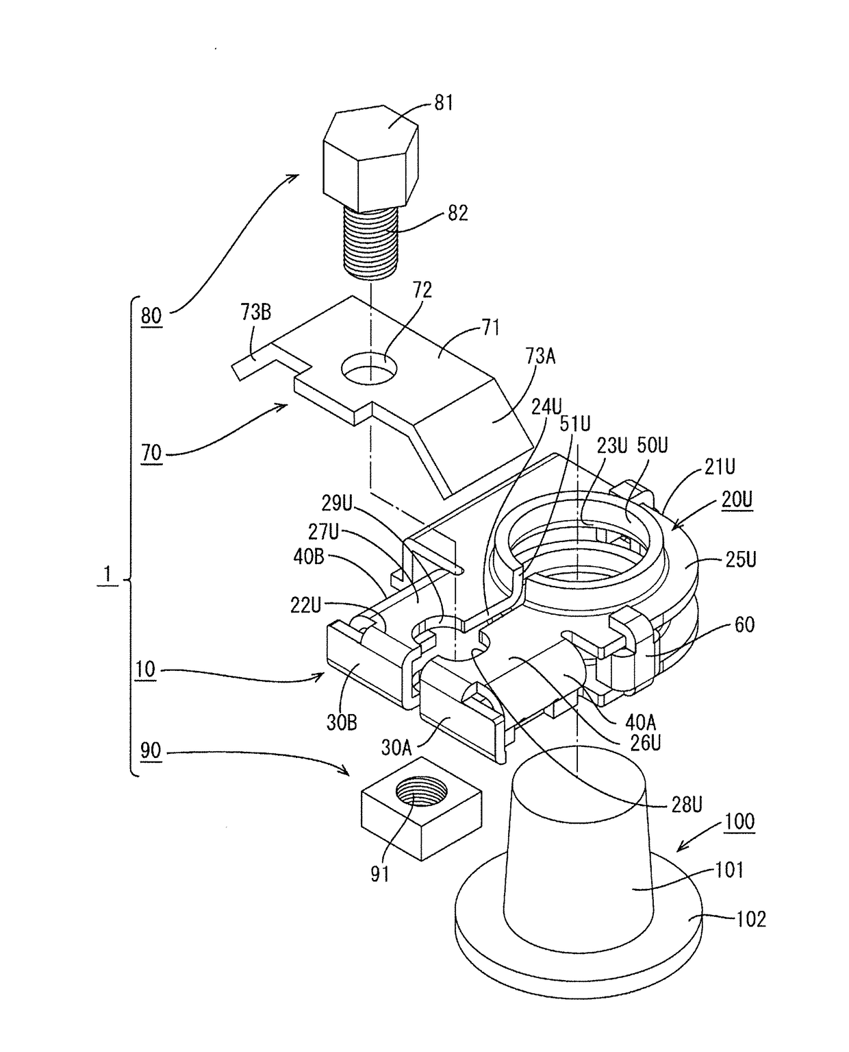
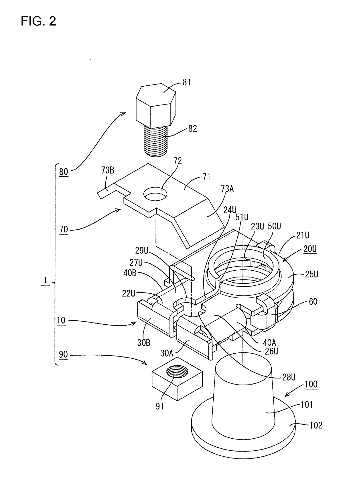
[0029]An embodiment of the present invention is described with reference to FIGS. 1 to 14. A battery terminal 1 of this embodiment is mounted on a battery post 100 provided on a battery (not shown) of a vehicle. The battery post 100 includes a cylindrical shaft 101 and a seat 102 arranged on one end of the shaft 101.

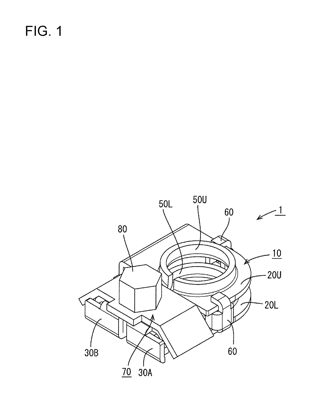
[0030]As shown in FIGS. 1 and 2, the battery terminal 1 includes a terminal main body 10, a bracket 70 (corresponding to a fastening member), a bolt 80 and a nut 90.

[0031]The terminal main body 10 includes an upper plate 20U, a lower plate 20L, first and second couplings 30A, 30B, first and second receiving portions 40A, 40B, upper and lower mounting tubes 50U, 50L and a plurality of stoppers 60.

[0032]As shown in FIG. 2, the upper plate 20U is a plate-like part long in one direction and has first and second short sides 21U, 22U perpendicular to a length direction. The upper plate 20U is arranged perpendicular to an axial direction of the shaft 101 of the battery post 100...


PUM


Abstract

A battery terminal (1) includes a main body (10) with upper and lower plates (20U, 20L). The upper plate (20U) includes an upper mounting hole (23U), and upper plate fastening portions (26U, 27U). The lower plate (20L) includes a lower mounting hole (23L) and lower plate fastening portions (26L, 27L). A first receiving wall (41A) is connected to a first upper plate fastening portion (26U) and engages a first lower plate fastening portion (26L). A second receiving wall (41B) is connected to the second upper plate fastening portion (27U) and engages the second lower plate fastening portion (27L). A bracket (70) is mounted on the main body (10) and has a first pressing portion (73A) with a first tapered surface (74A) to contact the first receiving wall (41A) and a second pressing portion (73B) with a second tapered surface (74B) to contact the second receiving wall (41B).

Description

BACKGROUND[0001]1. Field of the Invention[0002]The present invention relates to a battery terminal.[0003]2. Description of the Related Art[0004]A battery terminal is a member to be mounted on a battery post of a battery provided in a vehicle. A battery terminal manufactured by press-working one metal plate is disclosed in the Publication of Japanese Patent No. 4225405.[0005]The battery terminal disclosed in the Publication of Japanese Patent No. 4225405 includes a terminal main body and a bracket. The terminal main body is formed by bending one metal plate and includes an upper base plate and a lower base plate arranged in parallel to each other, and two couplings that couple the upper and lower base plates. Each of the upper and lower base plates includes a battery post insertion hole. Each of the two couplings is U-shaped, with one end part linked to the upper base plate and the other end part linked to the lower base plate. Each of the two couplings includes a slide contact porti...

Claims


Application Information

Patent Timeline
IPC IPC(8): H01M2/30H01R4/42H01M50/567
CPCH01M2/305H01R4/42H01M2220/20H01R13/207H01R11/285H01R13/621H01R11/283H01R11/281H01R4/5091H01R11/286Y02E60/10H01M50/567
Inventor YAMADA, RYOSUKEAMANO, TAKAMARUNAKANISHI, YUICHI
Owner SUMITOMO WIRING SYST LTD
Why Eureka
Try Eureka