Damping force-adjusting valve and shock absorber

Inactive Publication Date: 2019-05-02
KYB CORP
View PDF10 Cites 1 Cited by
  • Summary
  • Abstract
  • Description
  • Claims
  • Application Information

AI Technical Summary

Benefits of technology

[0007]In order to solve the problems, the invention provides a damping force-adjusting valve. The damping force-adjusting valve includes: a valve disc that includes an annular inner peripheral seat portion on which a leaf valve is stacked, an annular valve seat where the leaf valve is separated/seated, and an annular window provided between the inner peripheral seat p

Problems solved by technology

For this reason, there is a concern that abnormal noise may be generated.
Further, since the leaf valve is vigorously seated on the valve seat and a damping force is suddenly changed,

Method used


Image

  • Damping force-adjusting valve and shock absorber
  • Damping force-adjusting valve and shock absorber
  • Damping force-adjusting valve and shock absorber

Examples


Example

[0011]An embodiment will be described below with reference to the drawings. The same reference numerals given in several drawings denote the same components.

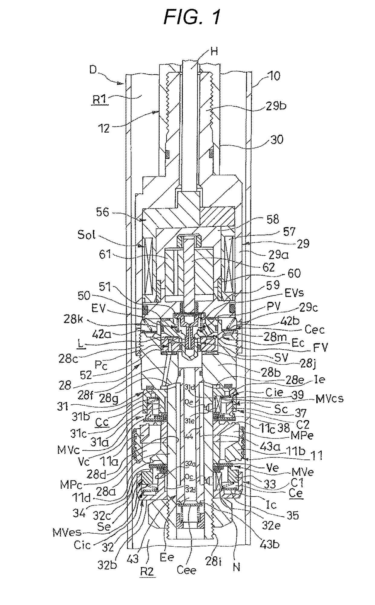
[0012]A shock absorber D according to this embodiment includes a cylinder 10 that is filled with liquid, such as hydraulic oil, a rod 12 that is movably inserted into the cylinder 10, and a piston 11 as an annular valve disc that is connected to one end of the rod 12 and partitions an inner space of the cylinder 10 into an extension-side chamber R1 and a compression-side chamber R2. Further, a damping force-adjusting valve V of this embodiment is realized on a piston part of the shock absorber D as illustrated in FIG. 1.

[0013]Furthermore, although not illustrated, a free piston is slidably inserted into a lower portion of the cylinder 10 in FIG. 1 and a gas chamber to be filled with gas is formed in the cylinder 10 below the compression-side chamber R2 in FIG. 1 by the free piston. Accordingly, in a case where the shock absorber...


PUM


Abstract

A damping force-adjusting valve includes: a valve disc that includes an annular inner peripheral seat portion on which a leaf valve is stacked, an annular valve seat where the leaf valve is separated/seated, and an annular window provided between the inner peripheral seat portion and the valve seat; and a sustaining portion that is provided between the inner peripheral seat portion and the valve seat and suppresses deformation of the leaf valve. An end of the sustaining portion facing the leaf valve more protrudes toward the leaf valve than an end of the valve seat facing the leaf valve when seen in an axial direction.

Description

TECHNICAL FIELD[0001]The present invention relates to a damping force-adjusting valve and a shock absorber.BACKGROUND ART[0002]As a shock absorber used for the suspension of a vehicle, there is a shock absorber including a damping force-adjusting valve that can change a damping force.[0003]Specifically, such a shock absorber includes a cylinder in which liquid is stored, a rod that is movably inserted into the cylinder, and a piston that is connected to one end of the rod and partitions an inner space of the cylinder into an extension-side chamber and a compression-side chamber. Further, a damping force-adjusting valve is realized on a piston part of the shock absorber. As disclosed in, for example, JP2015-72047(A), the damping force-adjusting valve uses a piston, which includes a passage allowing the extension-side chamber and the compression-side chamber to communicate with each other, as a valve disc, and includes the valve disc, an annular leaf valve that is stacked on the valve...

Claims


Application Information

Patent Timeline
IPC IPC(8): F16F9/348F16F9/46
CPCF16F9/3481F16F9/464F16F9/50F16F9/465F16F9/348F16F9/46
Inventor SAKUTA, ATSUSHI
Owner KYB CORP
Why Eureka
Try Eureka