Electromagnetic couplers for multi-frequency power detection

a technology of electromagnetic couplers and power detection, applied in the direction of electrical equipment, transmission, coupling devices, etc., can solve the problems of insertion loss, traditional em couplers add insertion loss to the signal path, and insertion loss in the em signal path

Active Publication Date: 2017-03-16
SKYWORKS SOLUTIONS INC
View PDF6 Cites 31 Cited by
  • Summary
  • Abstract
  • Description
  • Claims
  • Application Information

AI Technical Summary

Problems solved by technology

EM couplers typically cause an insertion loss in an EM signal path.
Insertion loss can be due to a portion of the EM signal being provided to the coupled port (or to the isolated port) and / or to losses associated with the main transmission line of the EM coupler.
In addition, traditional EM couplers add insertion loss to a signal path even when unused.
This can degrade an EM signal even when the EM coupler is not being used to detect power.

Method used


Image

  • Electromagnetic couplers for multi-frequency power detection
  • Electromagnetic couplers for multi-frequency power detection
  • Electromagnetic couplers for multi-frequency power detection

Examples


Embodiment Construction

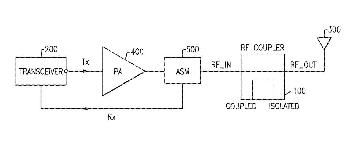
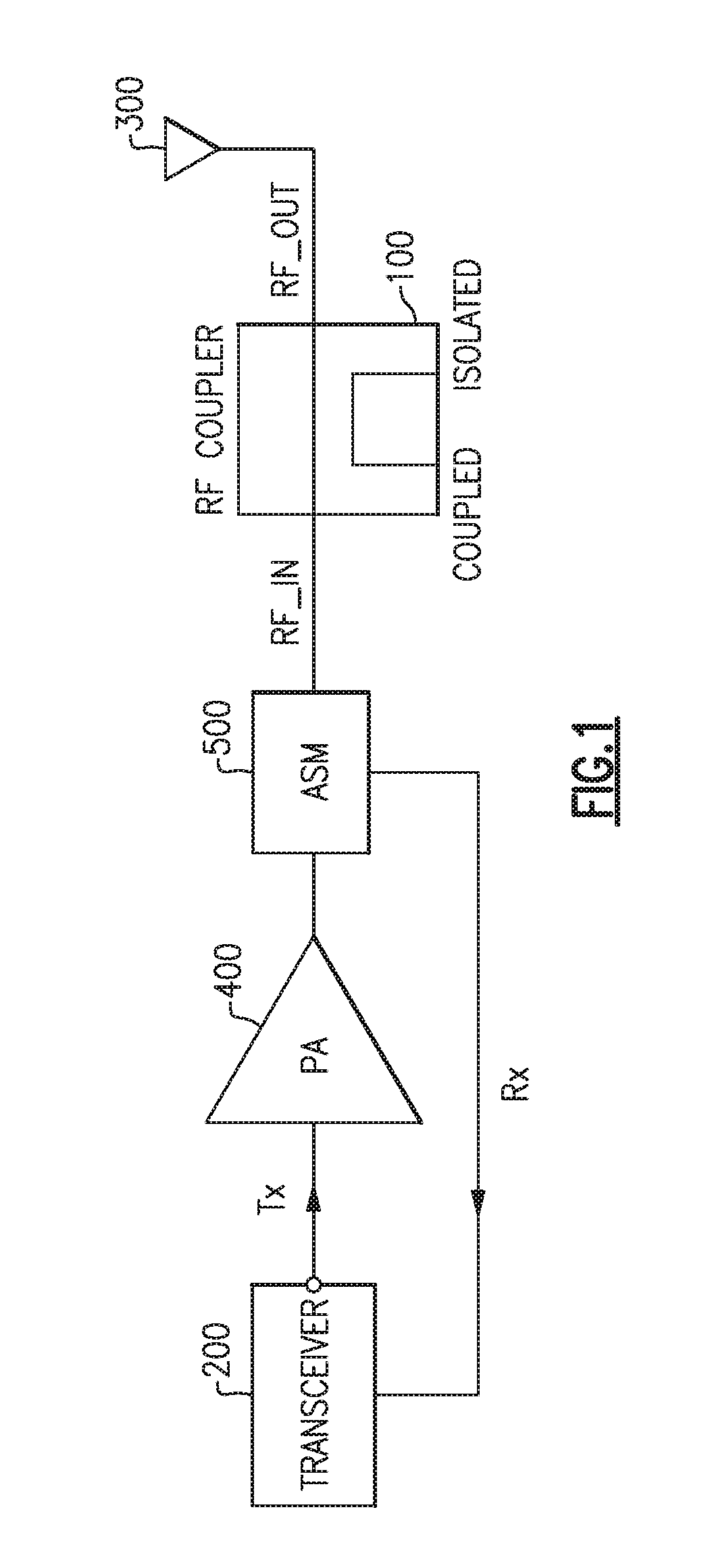
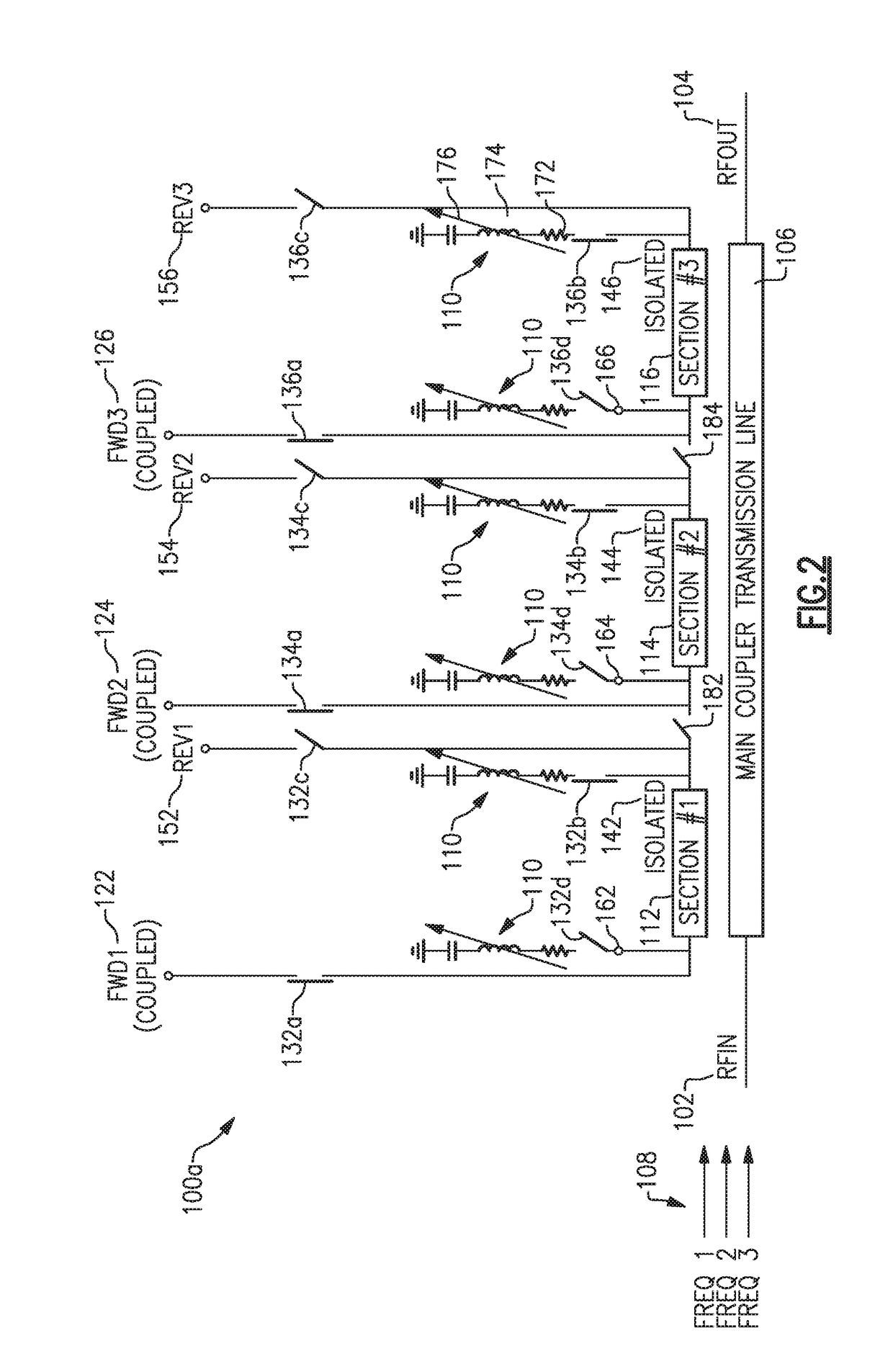
[0054]Bi-directional EM couplers have forward (FWD) and reverse (REV) coupled ports to couple signals received at either the input port (RFIN) or output port (RFOUT). The directivity of an EM coupler, which is a measure of how well the EM coupler provides a portion of power in only one direction and not the other, is dependent on the termination impedance. In a bi-directional EM coupler, when the forward coupled port is configured for the coupled mode, the reverse coupled port is terminated with an impedance selected to provide a high directivity for the forward coupled port, and vice versa. However, in conventional EM couplers, the termination impedance is typically at a fixed impedance value that provides a desired directivity only for a specific frequency or narrow band of frequencies around the specific frequency of interest. Thus, when operating outside of this frequency band, the directivity of the EM coupler will not be optimized.

[0055]Similarly, the coupling factor of an EM ...


PUM


Abstract

Multi-output electromagnetic couplers configured to detect multiple frequencies simultaneously, and devices and systems including same. In one example a multi-output electromagnetic coupler includes a main coupler transmission line extending between and electrically connecting an input port and an output port, a first coupled line section configured to couple electromagnetic power in a first frequency band from the main coupler transmission line to provide a first coupled output signal at a first coupled port, and a second coupled line section configured to couple electromagnetic power in a second frequency band from the main coupler transmission line to provide a second coupled output signal at a second coupled port simultaneously with the first coupled output signal being provided at the first coupled port.

Description

CROSS REFERENCE TO RELATED APPLICATIONS[0001]This application claims the benefit of priority under 35 U.S.C. §119(e) and PCT Article 8 to co-pending U.S. Provisional Patent Application No. 62 / 216,431 filed on Sep. 10, 2015, which is incorporated herein by reference in its entirety for all purposes.BACKGROUND[0002]Wireless devices generate electromagnetic (EM) signals, typically within the electromagnetic spectrum at a Radio Frequency (RF) capable of propagating to other wireless devices for communication purposes. When an electromagnetic signal generated by a source is provided to a load, such as to an antenna, a portion of the signal can be reflected back from the load. An electromagnetic coupler can be included in a signal path between the source and the load to provide an indication of forward power of the electromagnetic signal traveling from the source to the load and / or an indication of reverse power reflected back from the load. Electromagnetic couplers include, for example, ...

Claims


Application Information

Patent Timeline
Patent Type & Authority Applications(United States)
IPC IPC(8): H04B1/04H04B1/00H04B1/40
CPCH04B1/0458H04B1/0057H04B1/40H01P5/12H01P5/187
Inventor SRIRATTANA, NUTTAPONGWHITEFIELD, DAVID SCOTTSTORY, DAVID RYAN
Owner SKYWORKS SOLUTIONS INC
Why Eureka
Try Eureka