Stapler

a technology of stapler and stapler blade, which is applied in the direction of nails, nailing tools, fastening means, etc., can solve the problems of increasing the contact length between the workpiece and the cutting blade, increasing the penetration load, etc., and achieves the effect of suppressing the increase in the contact length of the cutting blade and increasing the penetration load

Active Publication Date: 2017-03-30
MAX CO LTD
View PDF5 Cites 1 Cited by
  • Summary
  • Abstract
  • Description
  • Claims
  • Application Information

AI Technical Summary

Benefits of technology

[0014]According to the stapler of the present disclosure, the deformation of the workpiece is suppressed in the penetrating operation of the cutting blade with respect to the workpiece, and thus...

Problems solved by technology

This causes the increase of a contact length between the work...

Method used


Image

  • Stapler
  • Stapler
  • Stapler

Examples


Embodiment Construction

[0128]An exemplary embodiment of a stapler according to the present disclosure will be described with reference to the accompanying drawings.

[0129]Exemplary Configuration of Stapler of the Embodiment

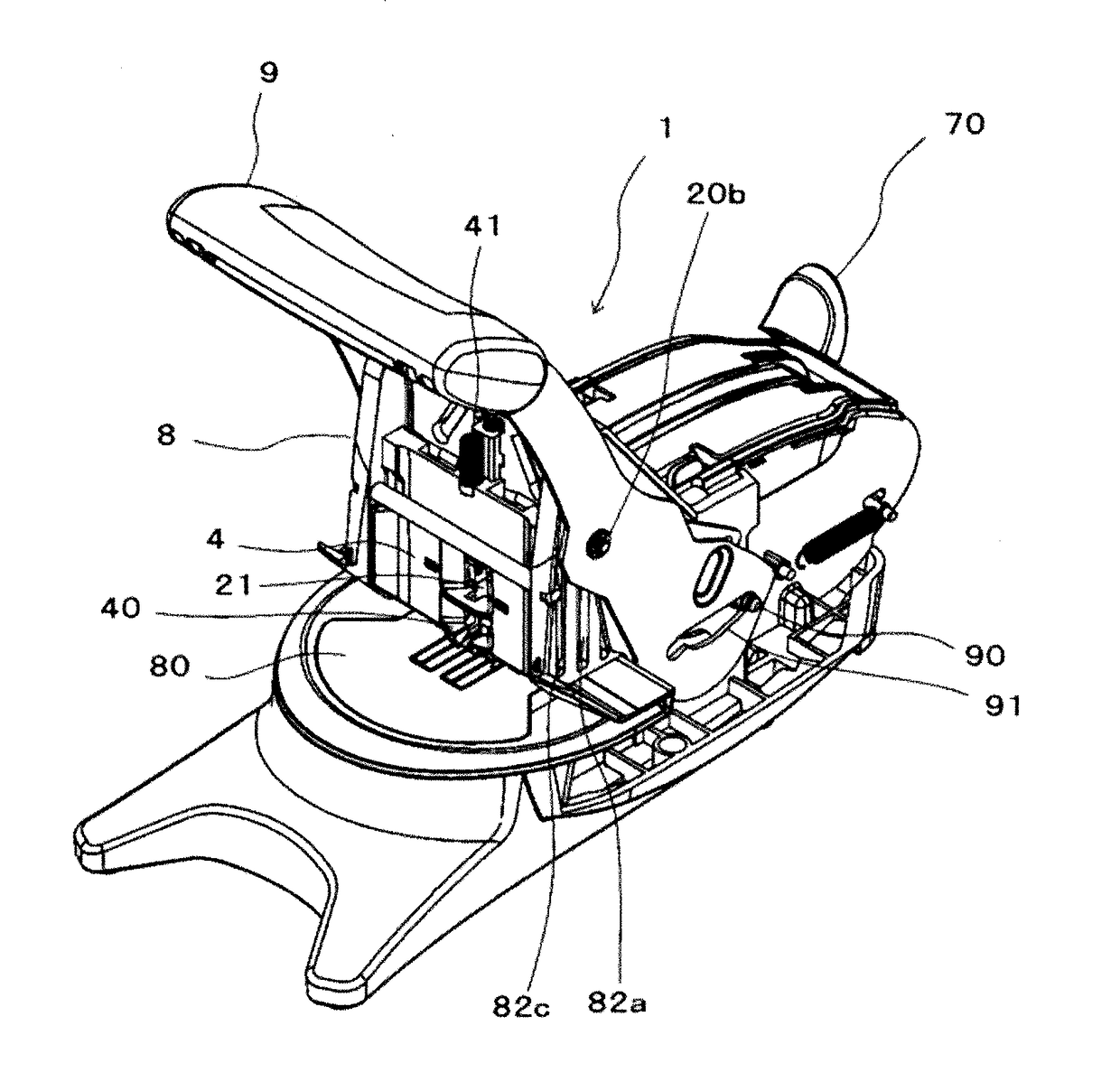
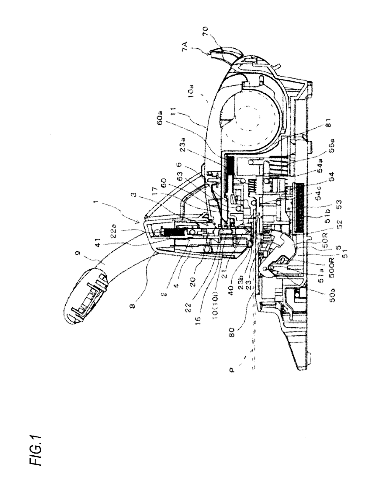
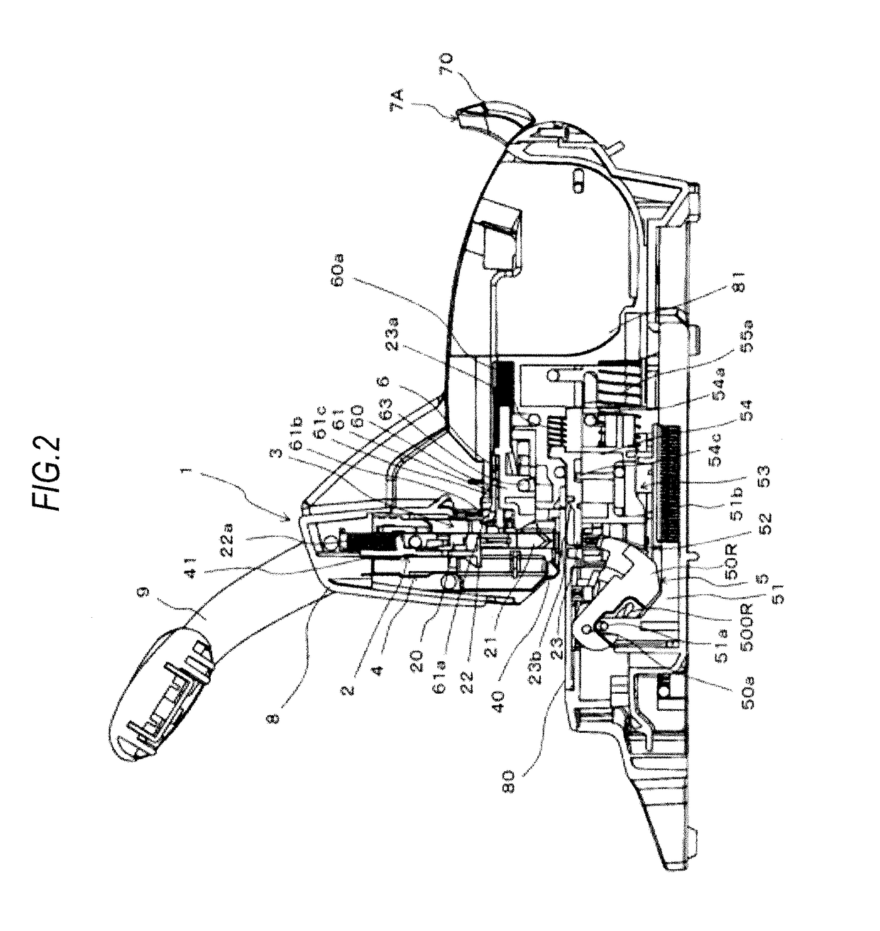
[0130]FIGS. 1 and 2 are side sectional views illustrating one example of an internal configuration of the stapler according to the embodiment, in which FIG. 1 shows a mounting state of a staple cartridge, and FIG. 2 shows a detached state of the staple cartridge. FIG. 3 is a side view illustrating one example of the stapler according to the embodiment.

[0131]FIG. 4 is a perspective view illustrating one example of the stapler according to one embodiment when seen from a front. FIG. 5 is a perspective view illustrating one example of the stapler according to this embodiment when seen from a rear. FIG. 6 is a forward sectional view illustrating one example of the internal configuration in a penetrating mechanism of the stapler according to this embodiment. FIG. 7 is a forward sectional view...


PUM


Abstract

A stapler is configured to bind a workpiece using a staple made of a non-metal soft material. The staple has a crown portion and a pair of leg portions formed by bending both longitudinal ends of the crown portion toward one direction. The stapler includes a placing base, a penetrating part, an opening, and a pressing portion. The opening is provided on the placing base so that the one pair of cutting blades and the one pair of leg portions of the staple inserted into the workpiece pass through the opening. The pressing portion that is provided in the opening of the placing base and suppresses deformation of the workpiece caused by a force applied to the workpiece from the cutting blades when the cutting blades penetrate the workpiece.

Description

CROSS-REFERENCE TO RELATED APPLICATION[0001]This application claims priorities from Japanese Patent Application No. 2015-186560 filed on Sep. 24, 2015, the entire contents of which are incorporated herein by reference.FIELD OF INVENTION[0002]The present disclosure relates to a stapler capable of stapling a workpiece using non-metal staples.BACKGROUND ART[0003]In related art, there has been proposed a stapler capable of stapling a workpiece using staples made of a non-metal material which is a soft material, such as paper, instead of metal staples.[0004]There has been proposed a stapler using staples made of such a non-metal soft material includes a pair of cutting blades for forming holes penetrating the workpiece and holding the staple, by which a pair of leg portions of the staple penetrate the workpiece when the one pair of cutting blades penetrate the workpiece.[0005]In the stapler using the staple made of the non-metal soft material, an opening is formed on a workpiece placing ...

Claims


Application Information

Patent Timeline
IPC IPC(8): B25C5/02F16B15/00
CPCF16B15/0015B25C5/0235B25C5/11B27F7/19B25C5/0214B25C5/0257
Inventor TAKAHASHI, HIROAKIKATO, YUTAKA
Owner MAX CO LTD
Why Eureka
Try Eureka