Suspension member lower arm bracket structure

a lower arm bracket and suspension member technology, applied in the direction of suspension arms, suspension components, understructures, etc., can solve the problems of deformation of the upper panel and lower panel of the lower arm bracket, and achieve the effect of increasing the number of components, increasing the strength of the lower arm bracket, and reducing the number of joints

Active Publication Date: 2017-03-30
TOYOTA JIDOSHA KK
View PDF0 Cites 2 Cited by
  • Summary
  • Abstract
  • Description
  • Claims
  • Application Information

AI Technical Summary

Benefits of technology

[0012]According to the second aspect, the vertical wall joint is formed in a ring shape around the inner periphery of the through-hole. Namely, configuration is made in which the join region is made larger, and an end portion in the length direction the vertical wall joint is not provided due to the vertical wall joint being continuous. Although stress is generally liable to concentrate at length direction end portions of vertical wall joints, in the configuration of the present disclosure there are no locations provided where stress is liable to concentrate, thereby enabling a joined state to be maintained. Accordingly, the join strength between the first vertical wall and the second vertical wall can be further increased.
[0013]The suspension member lower arm bracket structure according to the first aspect above enables the strength of the lower arm bracket to be increased, while suppressing an increase in the number of components.
[0014]The suspension member lower arm bracket structure according to the second aspect above enables the strength of the lower arm bracket to be further increased, while suppressing an increase in the number of components.

Problems solved by technology

However, if load from the lower arm is input to the lower arm bracket toward the vehicle rear side, there is a possibility that the upper panel and lower panel of the lower arm bracket will deform in directions separating from each other in the vehicle vertical direction, and a possibility that each will deform so as to bend.

Method used


Image

  • Suspension member lower arm bracket structure
  • Suspension member lower arm bracket structure
  • Suspension member lower arm bracket structure

Examples


first exemplary embodiment

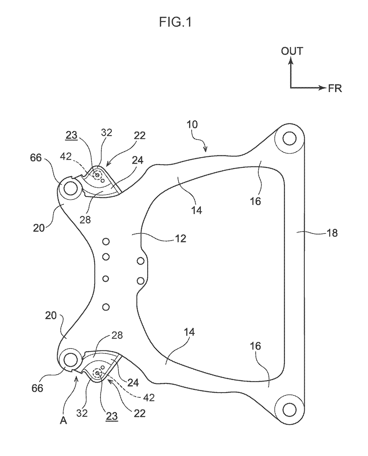
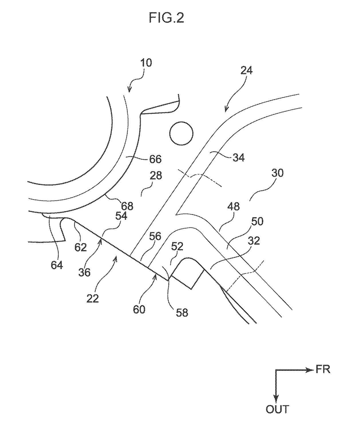
[0026]Explanation follows regarding an exemplary embodiment of a suspension member lower arm bracket structure according to the present disclosure, with reference to FIGS. 1 to 4. In the drawings, the arrow FR indicates a vehicle front-rear direction front side, the arrow OUT indicates a vehicle width direction outside, and the arrow UP indicates a vehicle vertical direction upper side.

[0027]As illustrated in FIG. 1, a suspension member 10, to which a suspension arm, a steering gear box (neither of which are illustrated in the drawings), and the like are attached, is provided to a front section of the vehicle. The suspension member 10 is disposed in an engine room at a vehicle lower side of a pair of left and right side members (omitted from illustration) that are disposed separated from each other in a vehicle width direction and that extend in the vehicle front-rear direction. The suspension member 10 is supported by the side members.

[0028]The suspension member 10 is formed substa...

second exemplary embodiment

[0051]Next, explanation follows regarding a suspension member lower arm bracket structure according to a second exemplary embodiment of the present disclosure, with reference to FIG. 6. Note that configuration parts similar to those of the first exemplary embodiment described above are allocated the same reference numerals, and explanation thereof is omitted.

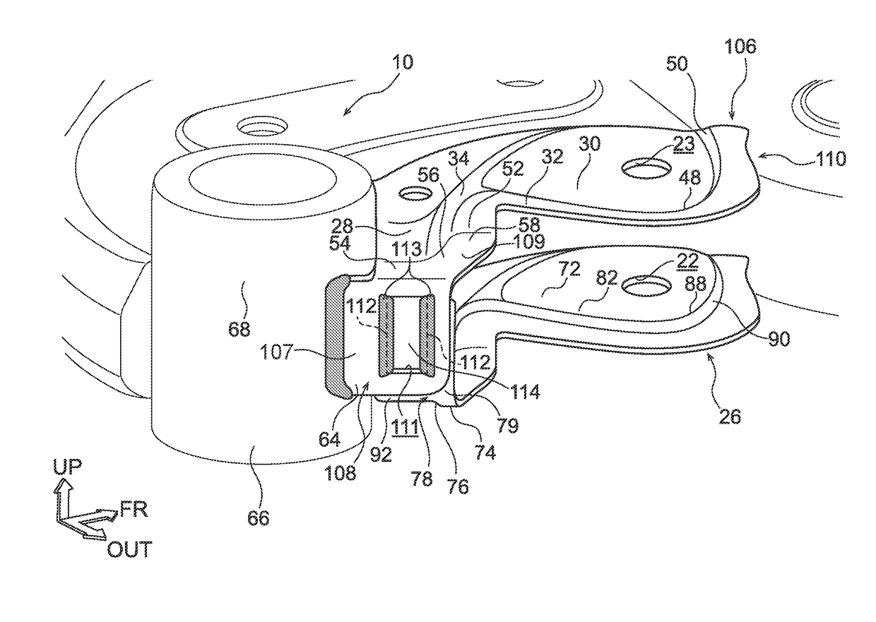
[0052]As illustrated in FIG. 6, a suspension member lower arm bracket structure according to the second exemplary embodiment is configured similarly as that of the first exemplary embodiment, but includes a feature of a first vertical wall 108 of an upper panel 106 and the second vertical wall 78 of a lower panel 26 being joined together by vertical wall joints 113 provided at inner peripheral portions of a through-hole 111 formed in the first vertical wall 108.

[0053]Namely, in a lower arm bracket 110, the first vertical wall 108 is connected to an end portion 56 in the vehicle width direction of the first coupling surface wall ...

third exemplary embodiment

[0060]Next, explanation follows regarding a suspension member lower arm bracket structure according to a third exemplary embodiment of the present disclosure, with reference to FIG. 8. Note that configuration parts similar to those of the first exemplary embodiment described above are allocated the same reference numerals, and explanation thereof is omitted.

[0061]As illustrated in FIG. 8, a suspension member lower arm bracket structure according to the third exemplary embodiment is configured similarly as that of the first exemplary embodiment, but includes a feature of a front side extension 122 of a first vertical wall 118 of an upper panel 116, and a front side extension 123 of a second vertical wall 119 of a lower panel 117, which extend in the vehicle vertical direction.

[0062]In a lower arm bracket 120, the first vertical wall 118 is connected to the end portion 56 in the length direction of the first coupling surface wall 34 of the upper panel 116, namely, in a direction along...


PUM


Abstract

A lower arm bracket is provided. A portion of the lower arm bracket is an upper panel that includes a first surface wall, a second surface wall, a third surface wall, a first coupling surface wall connecting the first surface wall and the second surface wall together, and a first vertical wall extending toward the vehicle lower side from a position including an end portion in the length direction of the first coupling surface wall. A portion of the lower arm bracket is configured by a lower panel that includes a fourth surface wall, a fifth surface wall, a sixth surface wall, a third coupling surface wall connecting the fourth surface wall and the fifth surface wall together, and a second vertical wall extending toward the vehicle upper side from a position including an end portion in the length direction of the third coupling surface wall.

Description

CROSS-REFERENCE TO RELATED APPLICATION[0001]This application claims priority under 35 USC 119 from Japanese Patent Application No. 2015-192284 filed on Sep. 29, 2015, the disclosure of which is incorporated by reference herein.BACKGROUND[0002]Technical Field[0003]The present disclosure relates to a suspension member lower arm bracket structure.[0004]Related Art[0005]Japanese Patent Application Laid-Open (JP-A) No. 2014-144658 describes a vehicle front section structure. More specifically, a lower arm that configures a portion of a suspension, and a suspension member that supports the lower arm are provided. A front side attachment portion of the lower arm is rotatably attached to a rod shaped front side arm attachment portion attached to an upper face of the suspension member, with the axial direction of the front side attachment portion of the lower arm in the vehicle front-rear direction. Moreover, a rear side attachment portion of the lower arm is rotatably attached through a bus...

Claims


Application Information

Patent Timeline
Patent Type & Authority Applications(United States)
IPC IPC(8): B60G7/00
CPCB60G2206/122B60G7/001B62D21/00B62D21/11
Inventor MORISHIGE, YUJI
Owner TOYOTA JIDOSHA KK
Why Eureka
Try Eureka