Apparatus and method for lifting and sliding a structure attached to the wall

a technology of apparatus and structure, applied in the field of apparatus and method for vertical lifting and sliding of structure attached to the wall, can solve the problems of high safety hazards, large quantity of high-altitude work, and inability to install such large vertical structures by integral lifting construction methods, and achieves convenient connection or disconnection between the lifter and the structure. , the effect of simple operation

Inactive Publication Date: 2017-03-30
GUANGZHOU DI ER CONSTR & ENG CO LTD +1
View PDF6 Cites 9 Cited by
  • Summary
  • Abstract
  • Description
  • Claims
  • Application Information

AI Technical Summary

Benefits of technology

[0015]Further, a slider is provided on the bottom of the lifting beam, and the contacting surface between the platform beam and the slider is smooth, such that smooth sliding can be achieved.
[0036]5. the connection between the lifter and the structure can be achieved by the lifting hangers and the steel beam on the structure, and the upper member of the hanger is connected with the lower member of the hanger via a hinge. This makes the connection or disconnection between the lifter and the structure convenient, with simple operation and high efficiency at altitude.

Problems solved by technology

However, since urban land is generally scarce, the area for construction is small, and temporary facilities for construction are arranged densely, it is impossible for installing such large vertical structures by integrally lifting construction methods.
(1) Assembly on site and large volume of welding;
(2) Large quantity of high-altitude work and high safety hazard;
(3) Poor operational environment condition for working on site, which makes it hard to guarantee construction quality, with low efficiency and long construction period.
When the push instrument kit is working and moving horizontally, the supporting points against the base will be moving forward accordingly, and thus the base of the push instrument kit must be connected and disconnected in turn to the supporters along the slide rails, which is time-wasting, energy-consuming and of safe risks.
Further such apparatus and method will be difficult to work if the structure to be lifted locates outside the building, for example, the structures attached to the external wall, such as glass curtain walls and steel work frames.
In case the apparatus and method disclosed by Chinese patent applications CN201310196541.1 and CN201310194901.4 are used, the operator has to operate the push instrument kit on the great cantilever, that is, the operator must be outside the building and proceed with the connection or disconnection between the base of the push instrument kit and the supporters (such as baffles or bolt holes) periodically along the rail or pathway of the push instrument kit, so that the safety is hard to be ensured.

Method used


Image

  • Apparatus and method for lifting and sliding a structure attached to the wall
  • Apparatus and method for lifting and sliding a structure attached to the wall
  • Apparatus and method for lifting and sliding a structure attached to the wall

Examples


Embodiment Construction

[0080]Preferred embodiments of the present invention would be described with reference to the drawings as follows. It should be understood that the preferred embodiments described here are only used for description and explanation, but not for limiting the present invention.

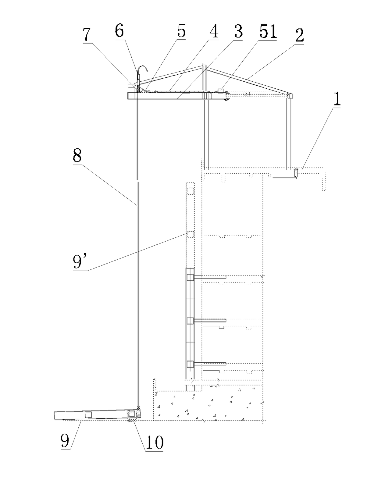
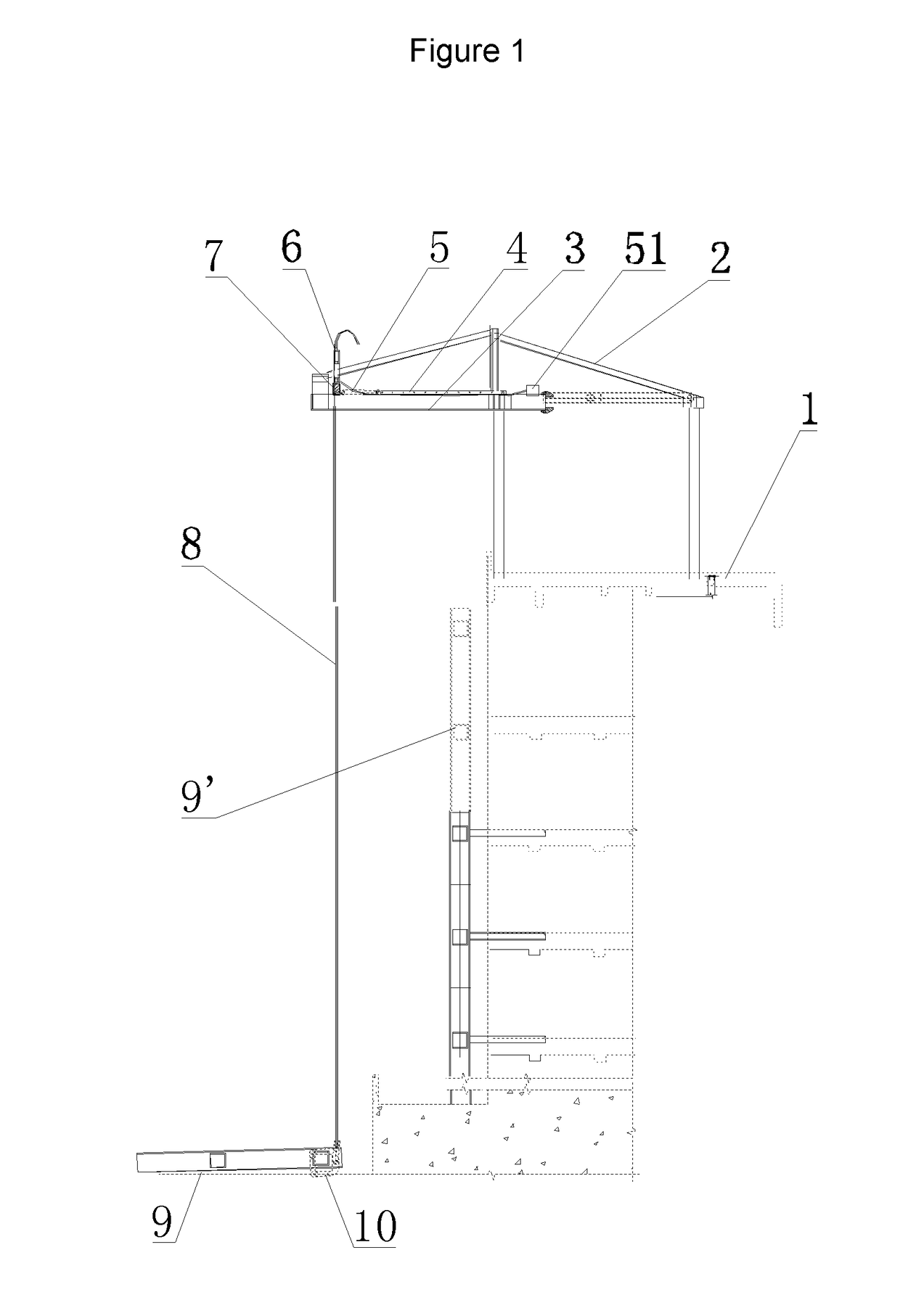
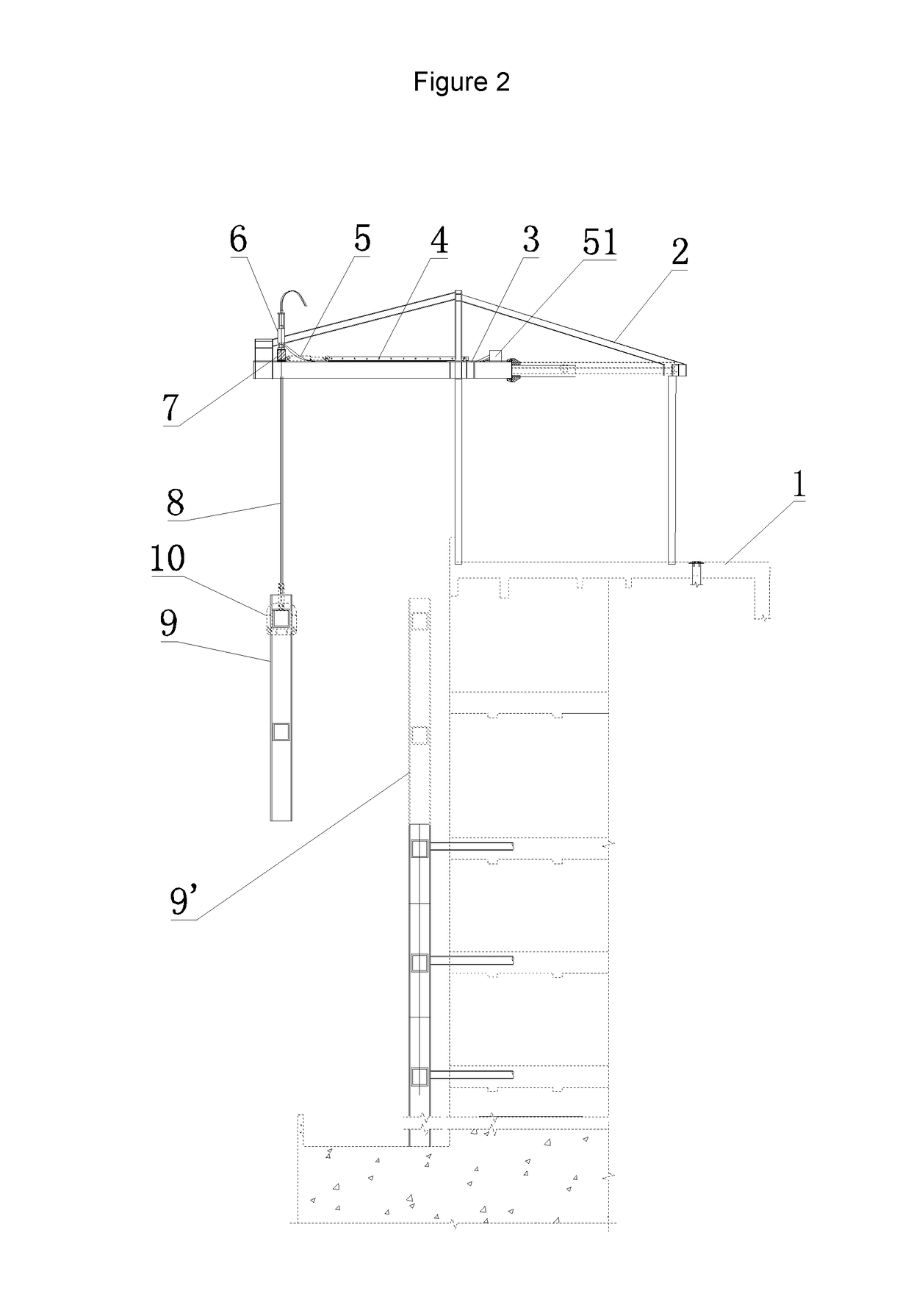
[0081]As shown in FIG. 1 to FIG. 5, the apparatus for lifting and sliding the structure attached to the wall according to the present invention comprises a lifting platform, and an apparatus for lifting and sliding which are arranged on the roof 1, wherein the lifting platform comprises a frame 2 and two platform beams 3 extending out over the building. A lifting beam 7 is placed on the platform beams 3.

[0082]The apparatus for lifting and sliding comprises a hydraulic lifter 6 fixed on the lifting beam 7, a hydraulic push instrument kit 5 arranged on the platform beam 3, and a controller 51 for controlling the hydraulic lifter 6 and the hydraulic push instrument kit 5.

[0083]The hydraulic push instrument kit 5 com...


PUM

PropertyMeasurementUnit
heightaaaaaaaaaa
flexibleaaaaaaaaaa
areaaaaaaaaaaa

Abstract

An apparatus for lifting and sliding a structure to be attached to a wall of a building, including a lifting platform extending outwardly from the building, and a synchronous lifting and sliding system which is arranged on the lifting platform. The lifting platform has two platform beams extending outwardly from the building, and a lifting beam placed on the platform beams. The synchronous lifting and sliding system has a hydraulic lifter arranged on the lifting beam, a hydraulic jack connected to the lifting beam, and a controller. A connecting rod is connected to one end of the hydraulic jack, and several installing holes are arranged at regular intervals on the connecting rod. The distance between the adjacent installing holes of the connecting rod matches a stroke of the hydraulic jack. An installing ear-plate is provided on the platform beam to connect with the connecting rod.

Description

CROSS REFERENCE TO RELATED APPLICATIONS[0001]This application is a Divisional of co-pending application Ser. No. 14 / 162,2016, filed on Jan. 23, 2014, for which priority is claimed under 35 U.S.C. §120; and this application claims priority of Application No. 201310503992.5 filed in China on Oct. 23, 2013, under 35 U.S.C. §119, the entire contents of which are hereby incorporated by reference.FIELD OF TECHNOLOGY[0002]The present invention relates to the field of construction technology, in particular the apparatus and method for lifting and sliding a structure attached to the wall vertically.BACKGROUND OF THE INVENTION[0003]With the development of society, the requirement on aesthetic, artistry and comfortability of the construction is higher and higher. Vertical steel grid structures are widely used in shaping and decorating the external walls of high buildings and super-high buildings, as it is aesthetic, light, and can be arranged in a flexible way. However, since urban land is gen...

Claims


Application Information

Patent Timeline
Patent Type & Authority Applications(United States)
IPC IPC(8): E04G21/00B66C23/20
CPCE04G21/00E04B2/88B66C23/205E04G21/167Y10T29/49904
Inventor WANG, LONGWEN, JIANMINGGAO, JUNYUEWEI, WEIZHAO, YUANTAOSHAO, QUANJIA, YANFENG
Owner GUANGZHOU DI ER CONSTR & ENG CO LTD
Why Eureka
Try Eureka