Device for locking a moving element such as an aircraft door and aircraft equipped with said locking device

Active Publication Date: 2017-03-30
AIRBUS SAS
View PDF12 Cites 2 Cited by
  • Summary
  • Abstract
  • Description
  • Claims
  • Application Information

AI Technical Summary

Benefits of technology

[0021]The invention makes it possible to obtain a locking device with a dual control based on pivoting elements (the first and second shafts), without links. This design makes it possible to reduce the number of parts and consequently to simplify the locking device and to reduce its weight.
[0022]According to another advantage, the fact of using only pivoting elements and of doing a

Problems solved by technology

These disadvantages are all the more detrimental in the case of a door of an aircraft hold si

Method used


Image

  • Device for locking a moving element such as an aircraft door and aircraft equipped with said locking device
  • Device for locking a moving element such as an aircraft door and aircraft equipped with said locking device
  • Device for locking a moving element such as an aircraft door and aircraft equipped with said locking device

Examples


first embodiment

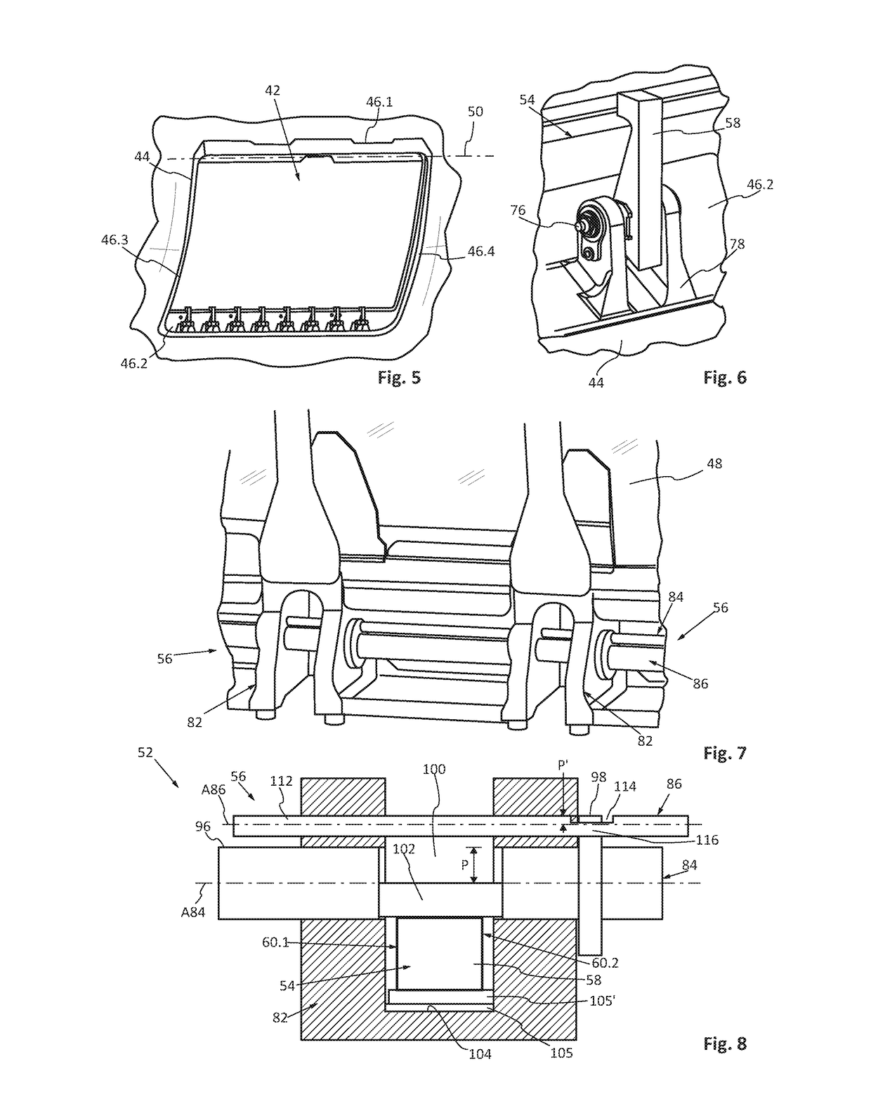
[0104]During functioning, the hook 58 therefore pivots around the axis A76 of the third shaft 76. the third shaft 76 has a diameter equal to that of the bore 70. In this case, the hook 58 can only pivot around the axis A76 of the third shaft 76.

second embodiment

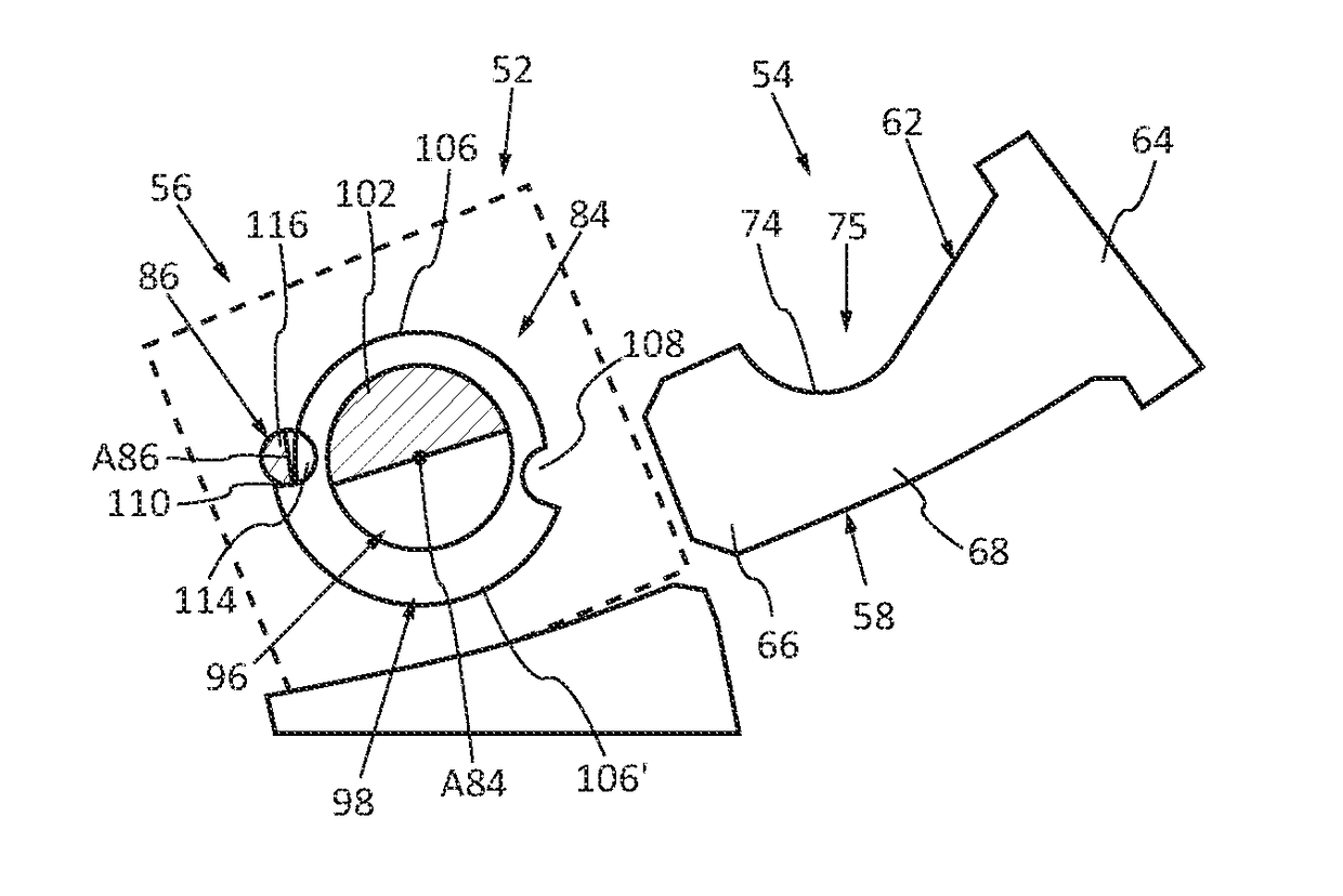
[0105] visible on FIG. 14, the third shaft 76 has a diameter smaller than that of the bore 70 and a ring 80 with an eccentric bore is interposed between the third shaft 76 and the bore 70. This embodiment allows, in addition to the rotating motion around the axis A76 of the third shaft 76, a slight deflection of the third shaft 76, allowing the hook 58 to be automatically positioned in relation to the second part 56 of the locking device integral with the door 48.

[0106]The invention is naturally not limited to the embodiment described above. The hook 58 can consequently equally be connected to the door or to the fuselage. Likewise, the use of the locking device is not limited to locking a door. It can consequently be used to lock a first mobile element of an aircraft in relation to a second fixed element.


PUM


Abstract

A locking device which includes a hook and a dual control for locking the hook. The dual control includes a first shaft and a second shaft. The first shaft incorporates a section and is rotationally mobile between a hooked position, in which the section is accommodated in a housing of the hook and an unhooked position, in which the section is outside the housing of the hook. The second shaft incorporates a section and is rotationally mobile between a locked position, in which the section of the second shaft is accommodated in a notch in a flange of the first shaft and an unlocked position, in which the section of the second shaft is outside the notch in the flange of the first shaft.

Description

CROSS-REFERENCES TO RELATED APPLICATIONS[0001]This application claims the benefit of the French patent application No. 1559034 filed on Sep. 25, 2015, the entire disclosures of which are incorporated herein by way of reference.BACKGROUND OF THE INVENTION[0002]This invention relates to a device for locking a moving element such as an aircraft door and to an aircraft equipped with said locking device.[0003]FIG. 1 shows an opening 10 in a fuselage 12 of an aircraft, FIG. 3 shows part of a door 14 configured for occluding the opening 10, and FIGS. 2, 3, 4A to 4C show a locking mechanism allowing the door 14 to be held in the closed position.[0004]According to an embodiment of the prior art, the locking mechanism includes a keeper 16 integral with the fuselage 12 and a hook 18 integral with the door 14.[0005]The keeper 16 is fixed and includes a cylinder 20, which has an axis oriented along a longitudinal direction and a clevis 22, which is integral with the fuselage and which supports t...

Claims


Application Information

Patent Timeline
IPC IPC(8): E05C19/00E05C9/18E05C3/12E05C9/08B64C1/14E05C19/12
CPCE05C19/002B64C1/1407E05C9/1808E05C3/12E05C9/08E05C19/12B64C1/1415B64D29/06
Inventor RABOIS, SERGE
Owner AIRBUS SAS
Why Eureka
Try Eureka