Oil passage structure for power transmission device

Active Publication Date: 2018-04-19
TOYOTA JIDOSHA KK +1
View PDF0 Cites 6 Cited by
  • Summary
  • Abstract
  • Description
  • Claims
  • Application Information

AI Technical Summary

Benefits of technology

[0025]According to the aspect, oil can be pumped to a plurality of oil supply destinations by the independent plate oil passages formed in the baffle plate. Accordingly, there is no need for providing a supply pipe for each oil supply destination, and the number of parts can be reduced.
[0026]According to the

Problems solved by technology

For example, in a case where the differential gear mechanism is used as an oil supply destination, the supply pipe is installed so as to bypass the baffle plate described in JP 2016-41979 A. In

Method used


Image

  • Oil passage structure for power transmission device
  • Oil passage structure for power transmission device
  • Oil passage structure for power transmission device

Examples


Embodiment Construction

[0040]Hereinafter, oil passage structures of power transmission devices in embodiments will be specifically described with reference to the drawings.

[0041]1. Overall Configuration

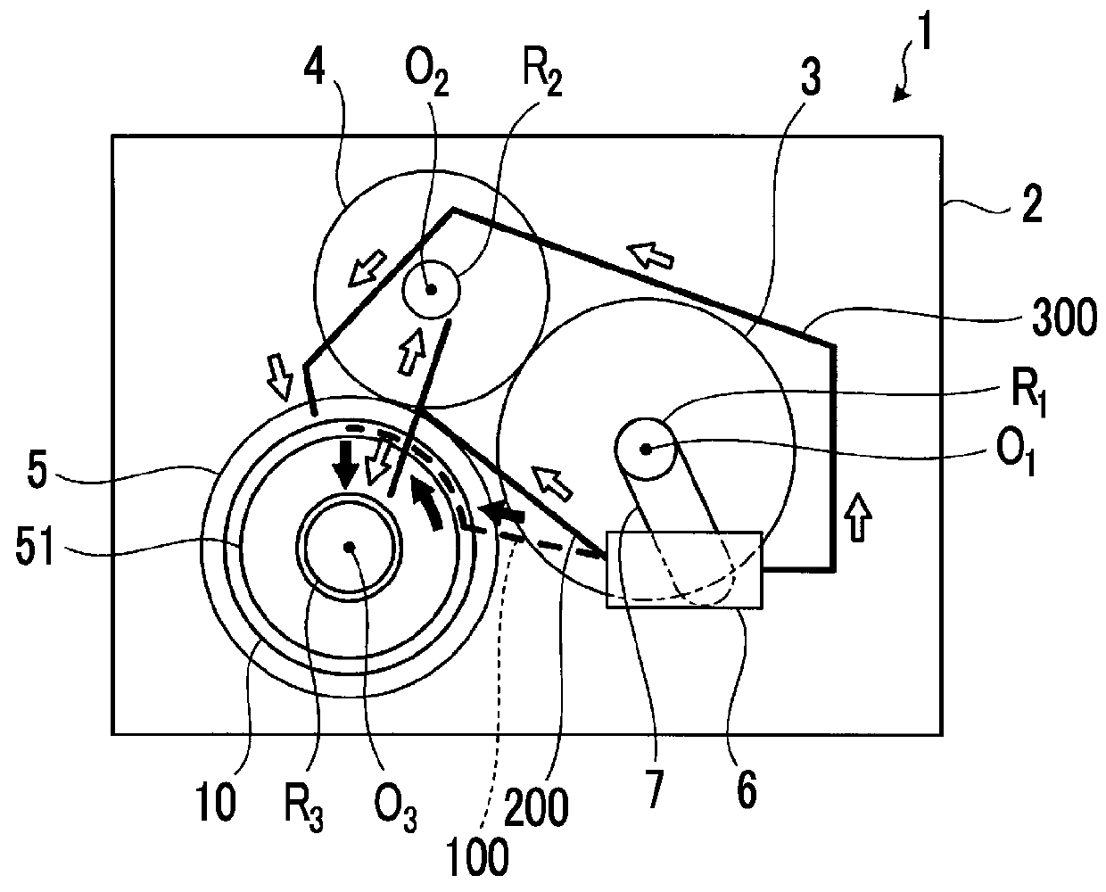
[0042]FIG. 1 is a schematic view for illustrating an oil passage structure for a power transmission device in an embodiment. In addition, for convenience of description, oil passages (a supply pipe 300 of the related art, an oil passage 200 that is the shortest path), which are not included in the embodiment, are illustrated in FIG. 1.

[0043]1-1. Power Transmission Device

[0044]A power transmission device 1 is a mechanism that is mounted on a vehicle in a state where the power transmission device is accommodated in a case 2 and that transmits the power, which is output from an engine, to the driving wheels. The power transmission device 1 illustrated in FIG. 1 is mounted on a front engine front drive type vehicle (FF vehicle), and includes a transmission 3, a counter gear mechanism 4, and a differential gear ...


PUM


Abstract

In an oil passage structure for a power transmission device including a case provided to accommodate a power transmission device, a baffle plate attached to an inner wall of the case, and an oil pump, the oil passage structure includes a supply oil passage through which oil is pumped from the oil pump to an oil supply destination via the baffle plate. The baffle plate has a structure in which two members of a plate body and a plate-shaped auxiliary member are superposed and integrated with each other. The baffle plate is provided with a plate oil passage that constitutes a portion of the supply oil passage and passes through the inside of the baffle plate. The plate oil passage is formed by a recess provided in at least one of a surface of the plate body and a surface of the auxiliary member which face to each other such that the auxiliary member is interposed on the plate body.

Description

INCORPORATION BY REFERENCE[0001]The disclosure of Japanese Patent Application No. 2016-203002 filed on Oct. 14, 2016 including the specification, drawings and abstract is incorporated herein by reference in its entirety.BACKGROUND1. Technical Field[0002]The present disclosure relates to an oil passage structure for a power transmission device.2. Description of Related Art[0003]Lubrication-needing sites that need lubrication using oil, such as engagement parts of gears and bearings, are provided inside a case provided to accommodate a power transmission device. As methods of supplying oil to the lubrication-needing sites, a method of pumping oil with an oil pump and oil passages, and a method (scooping lubrication) of scooping oil with a differential ring gear of a differential gear mechanism are known.[0004]Japanese Unexamined Patent Application Publication No. 09-026018 (JP 09-026018 A) discloses, as the method of pumping oil, connecting a supply pipe to oil passages formed in a ca...

Claims


Application Information

Patent Timeline
IPC IPC(8): F16H57/04F16H48/08
CPCF16H57/0423F16H48/08F16H57/0471F16H57/0479F16H57/0483F16H48/38F16H57/0421F16H57/0436F16H57/0445F16H2057/02091F16H2057/02095
Inventor KAWAKAMI, TAKAHOTABUCHI, MOTOKISAKAI, SHINYAOTA, KATSUHISAHIRANO, TATSUYAARIHATA, YOSHITO
Owner TOYOTA JIDOSHA KK
Why Eureka
Try Eureka