Flap actuating system for use in an aircraft

Active Publication Date: 2019-05-02
AIRBUS OPERATIONS GMBH
View PDF0 Cites 3 Cited by
  • Summary
  • Abstract
  • Description
  • Claims
  • Application Information

AI Technical Summary

Benefits of technology

[0024]The at least one bearing element may be provided in the form of a slide element forming a linear slide bearing. Thus, a carriage may be provided that is configured to be supported and guided along a linear slide bearing. Compared to known flap arrangements having a rolling-element bearing, such as ball bearings or roller bearings, for supporting and guiding a carriage of a flap, the use of a slide bearing has the effect that rolling elements can be omitted. Accordingly, the number of movable parts and thus the number of parts subjected to wear can be reduced. Further, rolling-element bearings may cause point loads between the rolling elements and a guiding rail or track. Upon moving the carriage, this can cause alternating and dynamic loads on local contact points inducing a risk of damaging to rail and roller. By providing a slide bearing, a contact surface between the slide elements and the slide rails is enlarged compared to rolling-element bearings, thereby providing a load-optimized design avoiding local contact points. Still further, the sliding couples of the slide bearing formed by the slide elements and the slide rails are preferably self-lubricating. As a result, a less complex and light-weight design of the carriage can be ensured that is also cost-efficient with respect to its manufacturing

Problems solved by technology

Such conventionally known flap arrangements have a complex construction requiring a complex s

Method used


Image

  • Flap actuating system for use in an aircraft
  • Flap actuating system for use in an aircraft
  • Flap actuating system for use in an aircraft

Examples


Embodiment Construction

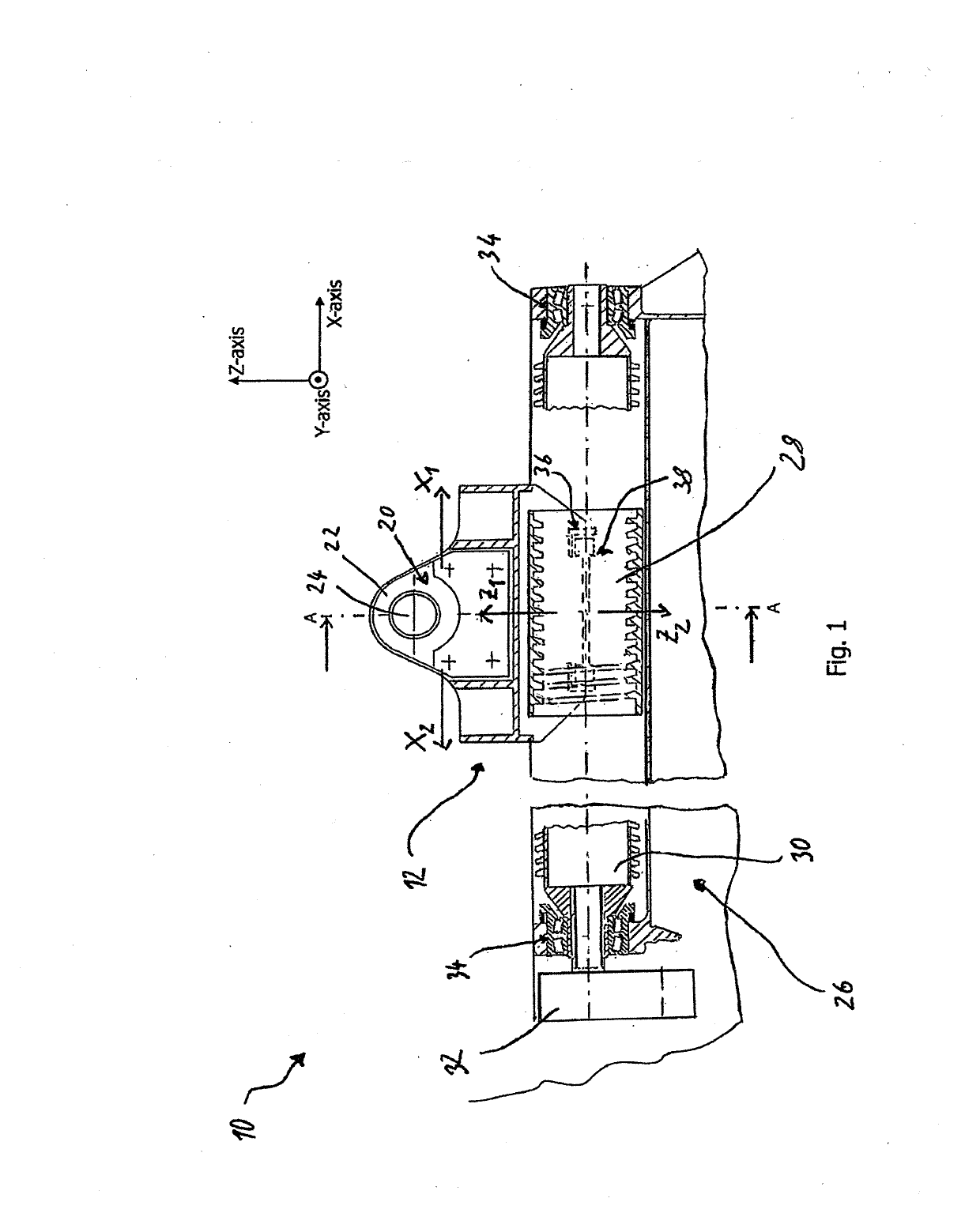
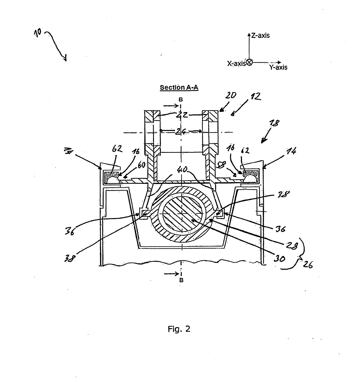
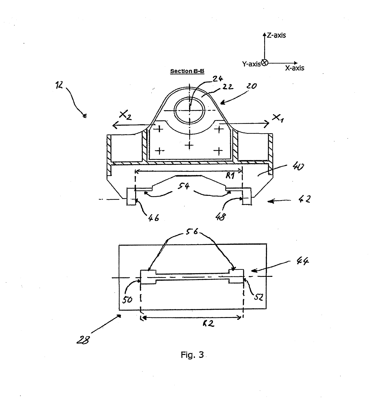
[0032]FIGS. 1 to 4 show a flap actuating system 10 for use in an aircraft according to a first embodiment for supporting and actuating a flap of the aircraft, which is not depicted in the figures. The supported and actuated flap preferably forms a part of an airfoil of the aircraft. Further, the flap is configured and design to, upon being actuated by the flap actuating system, move between an extended and retracted position.

[0033]For supporting and guiding the flap, the flap actuating system 10 comprises a carriage 12 which is engageable with and translationally movable along two linear bearing rails 14, as depicted in FIG. 2. The linear bearing rails 14 are fixedly connected to a main body of the airfoil. For engaging the carriage 12 with the linear bearing rails 14, the carriage 12 comprises two linear bearing elements 16, each of which is engaged with one of the linear bearing rails 14, respectively. The linear bearing rails 14, together with the bearing elements 16, form a line...


PUM


Abstract

A flap actuating system for use in an aircraft comprises a carriage for supporting and guiding a flap which is engageable with and translationally movable along at least one linear bearing rail. A linear actuator of the flap actuating system has a linearly actuatable coupling element coupled to the carriage and a drive element configured to linearly actuate the coupling element in a direction substantially parallel to a movement direction of the carriage along the linear bearing rail. The drive element is arranged substantially parallel to the movement direction of the carriage along the linear bearing rail.

Description

CROSS-REFERENCES TO RELATED APPLICATIONS[0001]This application claims the benefit of the German patent application No. 10 2017 125 382.3 filed on Oct. 30, 2017, the entire disclosures of which are incorporated herein by way of reference.BACKGROUND OF THE INVENTION[0002]The present invention refers to a flap actuating system for use in an aircraft.[0003]Aircraft airfoils are designed such that their geometry of the airfoil profile is adjustable or adaptable to the varying boundary conditions prevailing in different states of the course of a flight, such as during landing, take-off or cruise. Flap arrangements are known for selectively actuating a flap connected to an airfoil main body to extend into or retract from an air flow boundary layer of the airfoil so as to selectively vary the aerodynamic lift generated by the airfoil. Such conventionally known flap arrangements have a complex construction requiring a complex support and actuating mechanism for selectively extending and retr...

Claims


Application Information

Patent Timeline
IPC IPC(8): B64C13/28B64C9/02B64C9/14
CPCB64C13/28B64C9/02B64C9/14B64C3/50B64C13/34Y02T50/30
Inventor GARTELMANN, RAINER
Owner AIRBUS OPERATIONS GMBH
Why Eureka
Try Eureka