Engine

Inactive Publication Date: 2005-06-02
HONDA MOTOR CO LTD
View PDF3 Cites 12 Cited by
  • Summary
  • Abstract
  • Description
  • Claims
  • Application Information

AI Technical Summary

Benefits of technology

[0007] It is accordingly an object of the present invention to provide an engine which can reduce the number of parts, improve the mountability and maintainability, and further reduce the size and weight.
[0012] According to the present invention, the cylinder heads are integrated with portions of the cylinder barrels forming at least the cylinder bores to form the cylinder blocks. The cylinder blocks and the crankcase are fastened together under compression by the plurality of fastening bolts extending through at least the cylinder blocks. Accordingly, the machinability of the cylinder bores can be improved by forming the cylinder barrels and the crankcase as separate members. Further, any gasket for high temperature and high pressure that are conventionally required between each cylinder barrel and the corresponding cylinder head for the purpose of sealing between each combustion chamber and the outside can be eliminated. Accordingly, the number of bolts for fastening the crankcase, the cylinder barrels, and the cylinder heads can be reduced to thereby improve the mountability and maintainability.
[0013] Further, since the above-mentioned gasket is not provided, axial tensions of the fastening bolts can be controlled stably. In addition, it is sufficient for the fastening bolts to have a strength withstanding a tensile stress due to the combustion in the combustion chambers. Accordingly, the fastening bolts can be relatively reduced in number, and the diameter of each fastening bolt can be set to a relatively small value. Further, any fastening portion conventionally required between each cylinder barrel and the corresponding cylinder head can be eliminated, thereby obtaining an advantage in size and a reduction in the weight of the engine.
[0014] According to the present invention, size enlargement of the engine due to the location of the fastening bolts can be avoided, and the journal support walls of the left and right case halves can be firmly coupled together to support the crankshaft.

Problems solved by technology

Further, since the gaskets for high temperature and high pressure are interposed between the cylinder barrels and the cylinder heads, the fastening loads on the cylinder barrels and the cylinder heads must be set to a large value, so that the space and weight occupied by such fastening portions of the cylinder barrels and the cylinder heads become relatively large.

Method used


Image

  • Engine
  • Engine
  • Engine

Examples


Embodiment Construction

[0028] A preferred embodiment of the present invention will now be described with reference to the attached drawings.

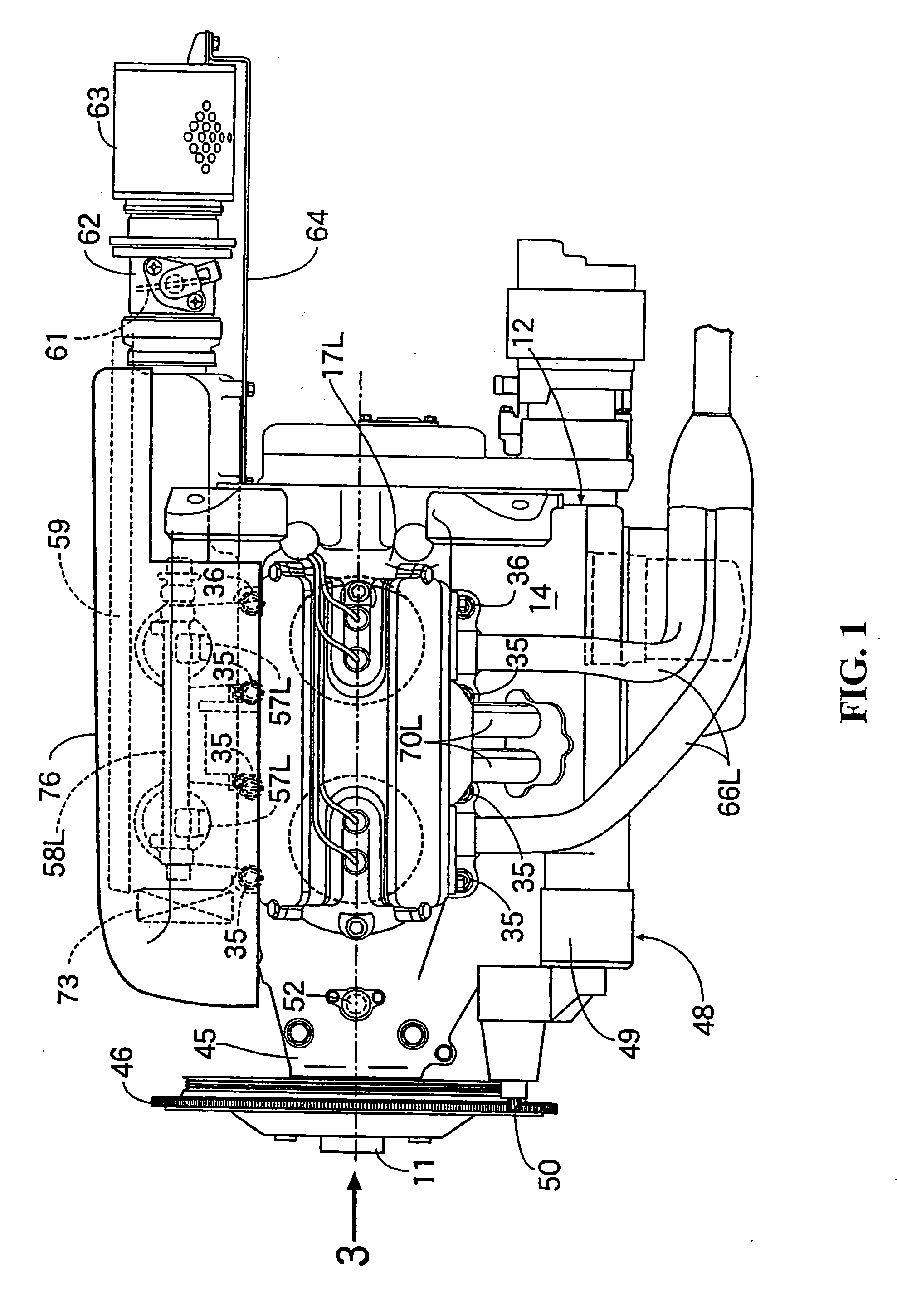
[0029] FIGS. 1 to 9 show a first preferred embodiment of the present invention wherein it is applied to a four-cycle, horizontally opposed, four-cylinder engine.

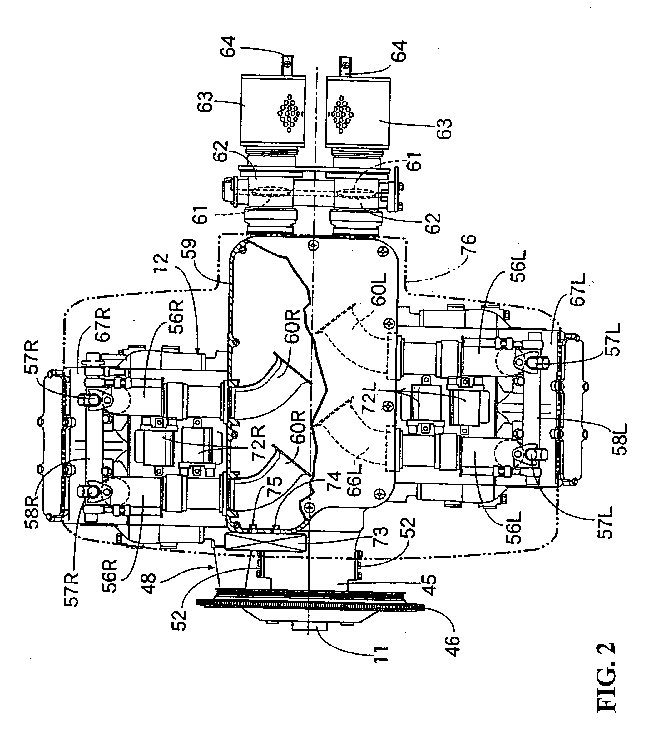
[0030] Referring first to FIGS. 1 to 3, the four-cycle, horizontally opposed, four-cylinder engine is adapted to be mounted on an aircraft in such a manner that the engine is accommodated in a front cowl of the body of the aircraft and the axis of a crankshaft 11 extends in the longitudinal direction of the body of the aircraft. A spinner having a plurality of propeller blades is coaxially connected to the crankshaft 11.

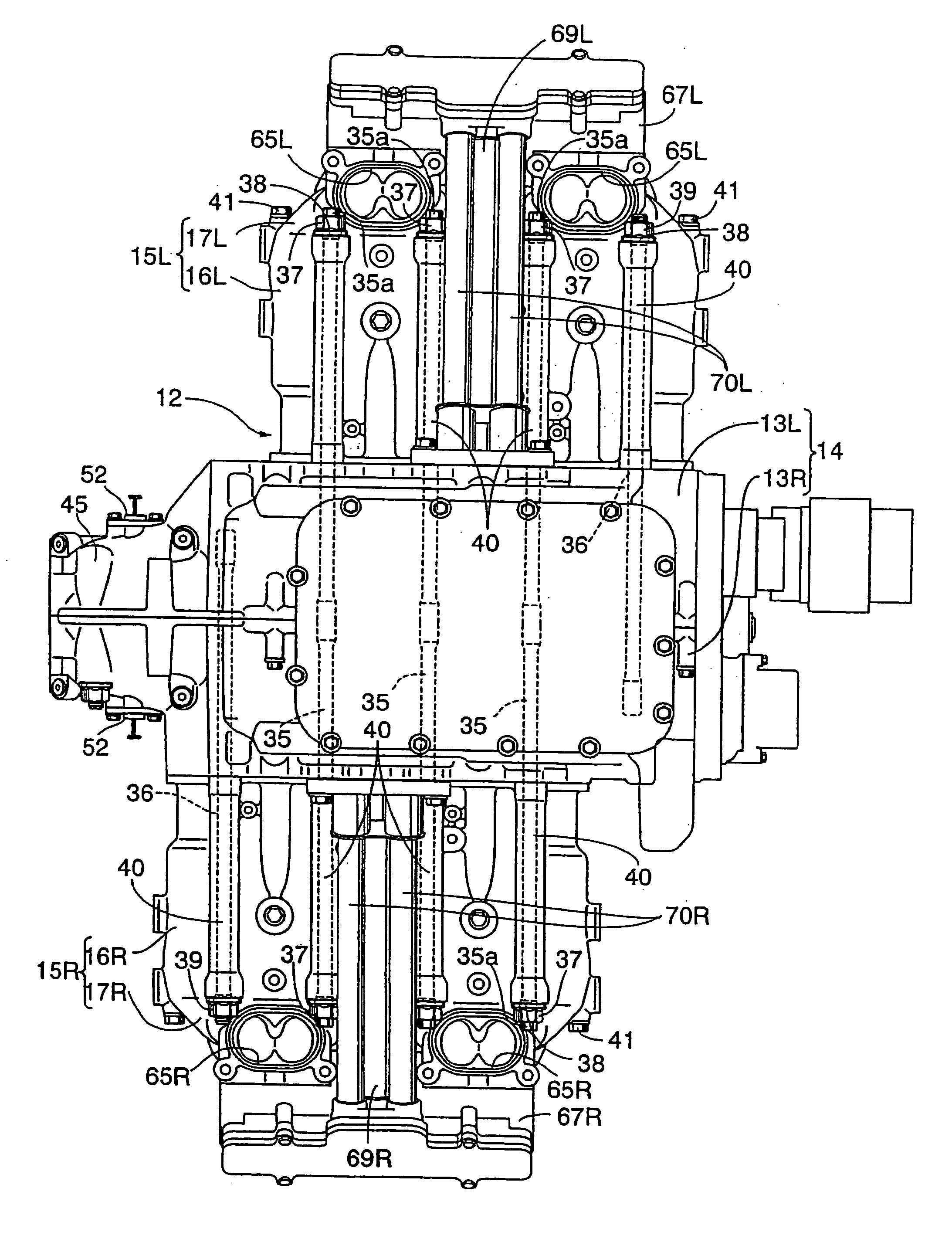
[0031] Referring also to FIG. 4, the engine has an engine body 12. The engine body 12 is composed of a crankcase 14, a left cylinder block 15L arranged on the left side of the crankcase 14, and a right cylinder block 15R arranged on the right side of the crankcase 14. The crankcase 14 is com...


PUM


Abstract

To reduce the number of parts, improve the mountability and maintainability, and allow for a reduction in the size and weight an engine is provided having a crankshaft, a crankcase having a plurality of bearing portions for rotatably supporting the crankshaft with each of the bearing portions being dividable along a divisional plane arranged on the axis of the crankshaft. Cylinder barrels are connected to the crankcase and include cylinder bores with cylinder heads connected to the cylinder barrels. The cylinder heads are integrated with portions of the cylinder barrels forming at least the cylinder bores to form cylinder blocks. The cylinder blocks and the crankcase are fastened together by a plurality of fastening bolts having axes parallel to the axes of the cylinder bores and extending through at least the cylinder blocks, with a compressive structure in the axial direction of the fastening bolts.

Description

CROSS-REFERENCE TO RELATED APPLICATIONS [0001] The present application claims priority under 35 USC 119 to Japanese Patent Application No. 2003-283027 filed on Jul. 30, 2003 the entire contents thereof is hereby incorporated by reference. BACKGROUND OF THE INVENTION [0002] 1. Field of the Invention Field [0003] The present invention relates to an engine, and more particularly to an engine having a crankshaft with a crankcase having a plurality of bearing portions for rotatably supporting the crankshaft, each of the bearing portions being dividable along a divisional plane arranged on the axis of the crankshaft. Cylinder barrels are connected to the crankcase with the cylinder barrels having cylinder bores with axes that are perpendicular to the divisional plane. The cylinder heads are connected to the cylinder barrels. [0004] 2. Description of Background Art [0005] In a conventional engine disclosed in Japanese Patent Laid-Open No. 2002-213302, for example, a crankcase, cylinder bar...

Claims


Application Information

Patent Timeline
IPC IPC(8): F02B75/18F02B75/24F02F1/00F02F7/00
CPCF02B75/243F02F7/0046F02F1/002F02B2075/1816
Inventor SANADA, MAKOTOHASEGAWA, SHUMPEIMATSUDA, MINORU
Owner HONDA MOTOR CO LTD
Why Eureka
Try Eureka