
gasket

a technology of gaskets and gaskets, applied in the field of gaskets, can solve the problems of affecting the sealing effect of flange joints, so as to reduce the corrosion reaction and prevent the effect of corrosion

Active Publication Date: 2017-03-30
FLEXITALLIC INVESTMENTS
View PDF1 Cites 0 Cited by
  • Summary
  • Abstract
  • Description
  • Claims
  • Application Information

AI Technical Summary

Benefits of technology

The patent describes a gasket made of a special material called biaxially orientated PTFE containing hollow glass microspheres. This material has advantages over traditional gaskets by reducing cold flow and allowing for better delivery of chemical treatment agents. The inner portion of the gasket can compress into any imperfections in the mating surfaces, sealing them and preventing further damage. The material can also micro-seal the imperfections by forming a seal around the edge of the surface. The gasket can be secured in position in a joint using a fixation lug and an extension. The extension is frangible and can be easily removed after the gasket is secured. The inner portion material has the added benefit of being able to passivate corrosion cells by reacting with iron, reducing the risk of corrosion. Overall, this gasket design improves leakage characteristics and extends the life of joints in corrosive environments.

Problems solved by technology

In many applications however the flange joint mating surfaces which are typically metal eventually become damaged either by internal chemical corrosion, erosion or external weathering.
This attrition of the surface can cause pitting, crevices and other imperfections to form on the surface.
In such cases, replacement of an ordinary sealing gasket will not be sufficient to effect adequate sealing under operational pressures because the surface imperfections may provide fluid escape pathways and weak points in the surface sealing.
However, in cases of mating surfaces which have become pitted or corroded even such high pressure gaskets cannot always provide adequate sealing.
Preferably, the mating surfaces have been damaged by corrosion.
The thin sections are strong enough to keep the extension attached to the main gasket during normal storage, transport and fitting conditions but weak enough to allow easy removal under a suitable force applied by the user after joint fixation.
Also, in the presence of water (and the potential beginning of a corrosion cell) the anion can be released and react with any iron available on the flange surface, passivating it, and thus making it more difficult for a corrosion cell to initiate.

Method used


Image

  • gasket
  • gasket
  • gasket

Examples


Embodiment Construction

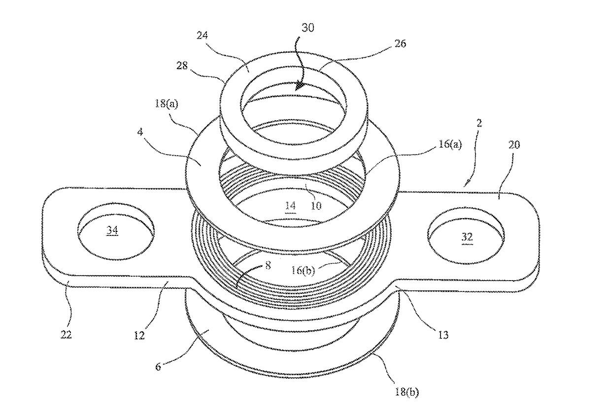
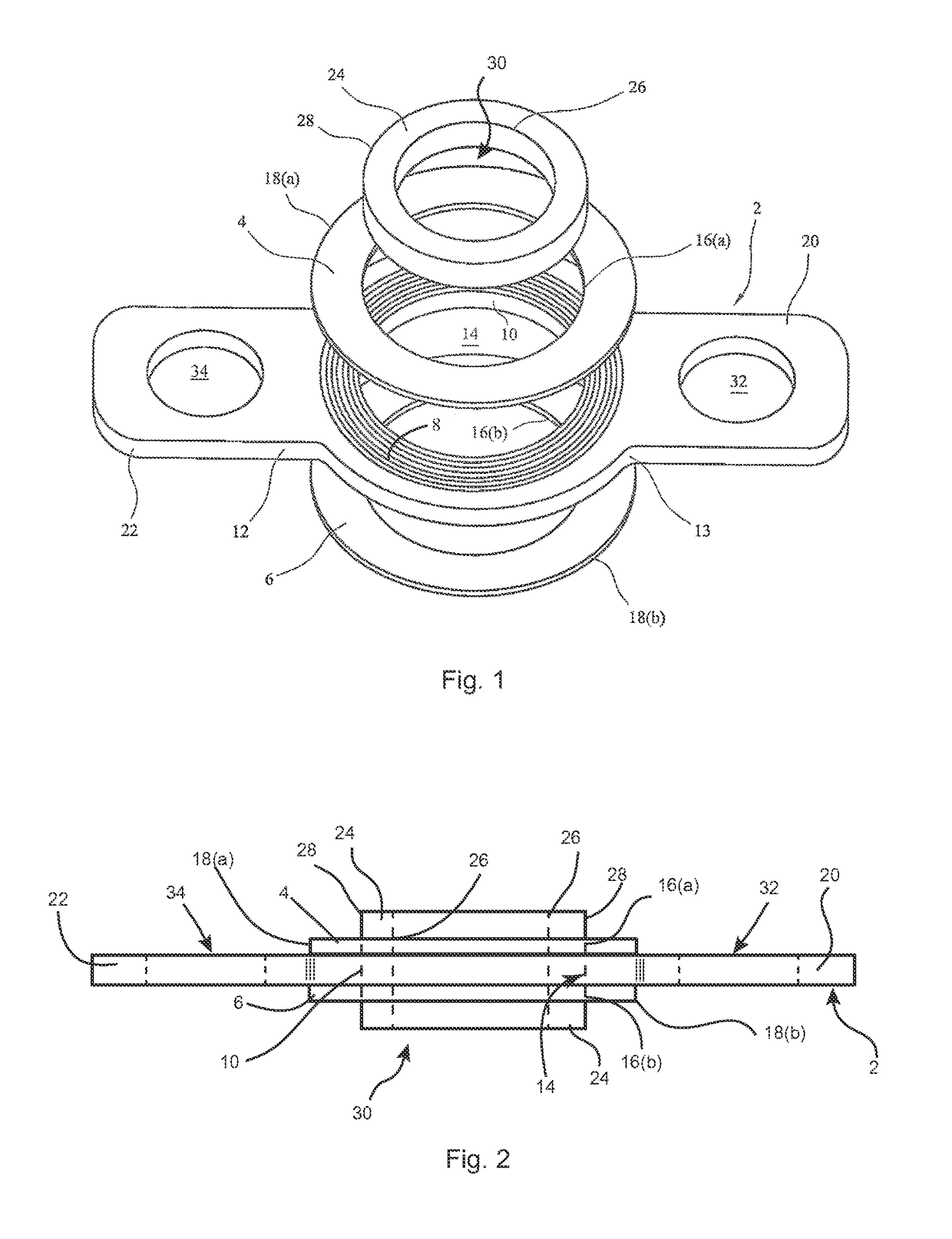
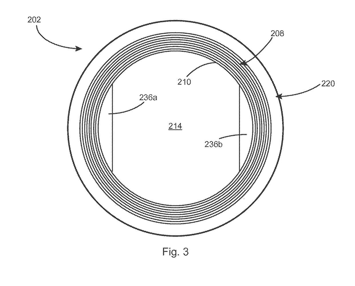
[0058]Referring to FIGS. 1 and 2, a corrugated gasket core 2 is shown having a corrugated area 8 extending outwardly from an inner edge 10 defining a first aperture 14 to a plane surfaced outer area 12. FIG. 1 shows the core 2 prior to complete covering of the upper and lower surface of the corrugated area 8 with respective PTFE sealing rings 4, 6 having inner edges 16a, 16b which also define the first aperture 14 and outer edges 18(a), 18(b) which terminate at the outer edge of the corrugated area 8 when affixed to the surface of the core. FIG. 2 shows a side view of the assembled gasket. The core 2 includes handling lugs 20, 22 extending outwardly from the plane surface area 12 on opposite sides of the gasket core. Each lug 20, 22 is integral with the core and has a centrally disposed hole 32, 34 to accommodate a fixing bolt (not shown) when locating the gasket in the flange joint.

[0059]Referring to FIG. 3, a corrugated gasket core 202 is shown having a corrugated area 208 extendi...


PUM


Abstract

A method for fluidly sealing two conduits having mating surfaces is described. The method includes positioning a gasket between the surfaces, securing the two conduits together with the gasket interposed between the mating surfaces wherein the gasket includes an outer seal with a first thickness and an inner seal with a thickness greater than that of the outer seal. The step of positioning and / or the step of securing includes compressing the thickness of the inner seal. Methods of making the gaskets are also disclosed.

Description

CROSS-REFERENCE TO RELATED APPLICATION[0001]This application is a divisional of U.S. application Ser. No. 12 / 976,097, now allowed, which claims the benefit of Great Britain Patent Application No. 0922625.9 filed on Dec. 24, 2009, the contents of all which are incorporated herein by reference in their entireties.FIELD OF THE INVENTION[0002]The present invention relates to gaskets, in particular, but not exclusively, flange joint sealing gaskets with an especially advantageous application as a replacement flange joint sealing gasket.BACKGROUND OF THE INVENTION[0003]The use of gaskets in sealing applications is commonplace in many industries. A well-known application for gaskets is to provide fluid sealing between two mating surfaces such as between two ends of adjoining pipes or conduits where they are commonly in the form of a flange joint for ease of assembly and disassembly and for better sealing. A flange joint sealing gasket usually comprises a compressible ring defining an apert...

Claims


Application Information

Patent Timeline
IPC IPC(8): F16L23/18F16J15/10F16L58/18F16J15/12F16J15/06
CPCF16L23/18F16J15/121F16J15/102F16L58/187F16J15/064
Inventor BOND, STEPHEN PETERCURRIE, ANTHONY RUSSELLWOOLFENDEN, STEPHENKIRBY, DEAN JOHN
Owner FLEXITALLIC INVESTMENTS
Learn More