Flange for connecting a vibration damper tube to a module tube of a vibration damper

a technology of vibration damper and module tube, which is applied in the direction of vibration dampers, springs/dampers, shock absorbers, etc., can solve the problem that the maximum possible spacing between the module tube and the vibration damper tube is structurally limited, the connection between the module tube and the vibration damper tube cannot be formed only by the transfer rings

Active Publication Date: 2017-04-06
THYSSENKRUPP BILSTEIN +1
View PDF1 Cites 0 Cited by
  • Summary
  • Abstract
  • Description
  • Claims
  • Application Information

AI Technical Summary

Benefits of technology

[0020]With special benefit, the retaining means can be designed with a wrap-around strip at the edges of the plastic body, while the wrap-around strips can be shorter in their lengthwise extension than the grooves. In this way, the end faces of the plates can be clearly exposed over their entire height, and if a weld seam is produced to weld the plates to the tubes the end faces of the plates will be clearly exposed in the area adjacent to the tubes, without a wrap-around strip of the retaining means to form the grooves covering the welding region of the end faces.

Problems solved by technology

The maximum possible spacing between the module tube and the vibration damper tube here is structurally limited by the design of the transfer rings.
Because of the heavy dynamic loading of a vibration damper tube, great mechanical strength of the module tube on the vibration damper tube is required, and if the spacing between the module tube and the vibration damper tube needs to be increased, for example, for design reasons, then the flange connection between the module tube and the vibration damper tube can no longer be formed only by transfer rings, since these are not sufficiently mechanically loadable.
Although a flange can be made from a metallic material affording a good strength between the module tube and the vibration damper tube, especially when the tubes are welded to the flange, a flange made from a solid metallic material for example can quickly have a large weight.
A flange made from a plastic material would be lighter, but it would not achieve the required strength, and the module tube would not be mounted with adequate mechanical strength on the vibration damper tube.
For example, if a flange is made of a solid metallic material, the further problem arises of the sealing of the fluid ducts to the tube bodies.
If the connection between the flange and the tubes is formed by a welded connection, the difficulty arises of the seal between the fluid ducts in the flange and the outside of the tubes.
By a combination of a plastic body, in which at least one fluid duct is formed, and by additional connection elements the weight of a flange can be reduced, although the design and especially the mounting of the flange can be made more difficult, even with higher.
This requires a costly welding device.
To produce the H-shaped connection element, several stamping and bending operations and further welding processes are needed, so that the flange formed in this way has a costly fabrication.
The transition body has to be made in a costly manner by a forming process and the contact surfaces of the transition body must be adapted to the envelope surfaces of the tubes.
Consequently, the welding processes have to be interrupted by the inserting of the plastic body, making the mounting of the flange more difficult.

Method used


Image

  • Flange for connecting a vibration damper tube to a module tube of a vibration damper
  • Flange for connecting a vibration damper tube to a module tube of a vibration damper
  • Flange for connecting a vibration damper tube to a module tube of a vibration damper

Examples


Embodiment Construction

[0022]Further measures which improve the invention shall be presented more closely below together with the description of a preferred sample embodiment of the invention by means of the figures. There are shown:

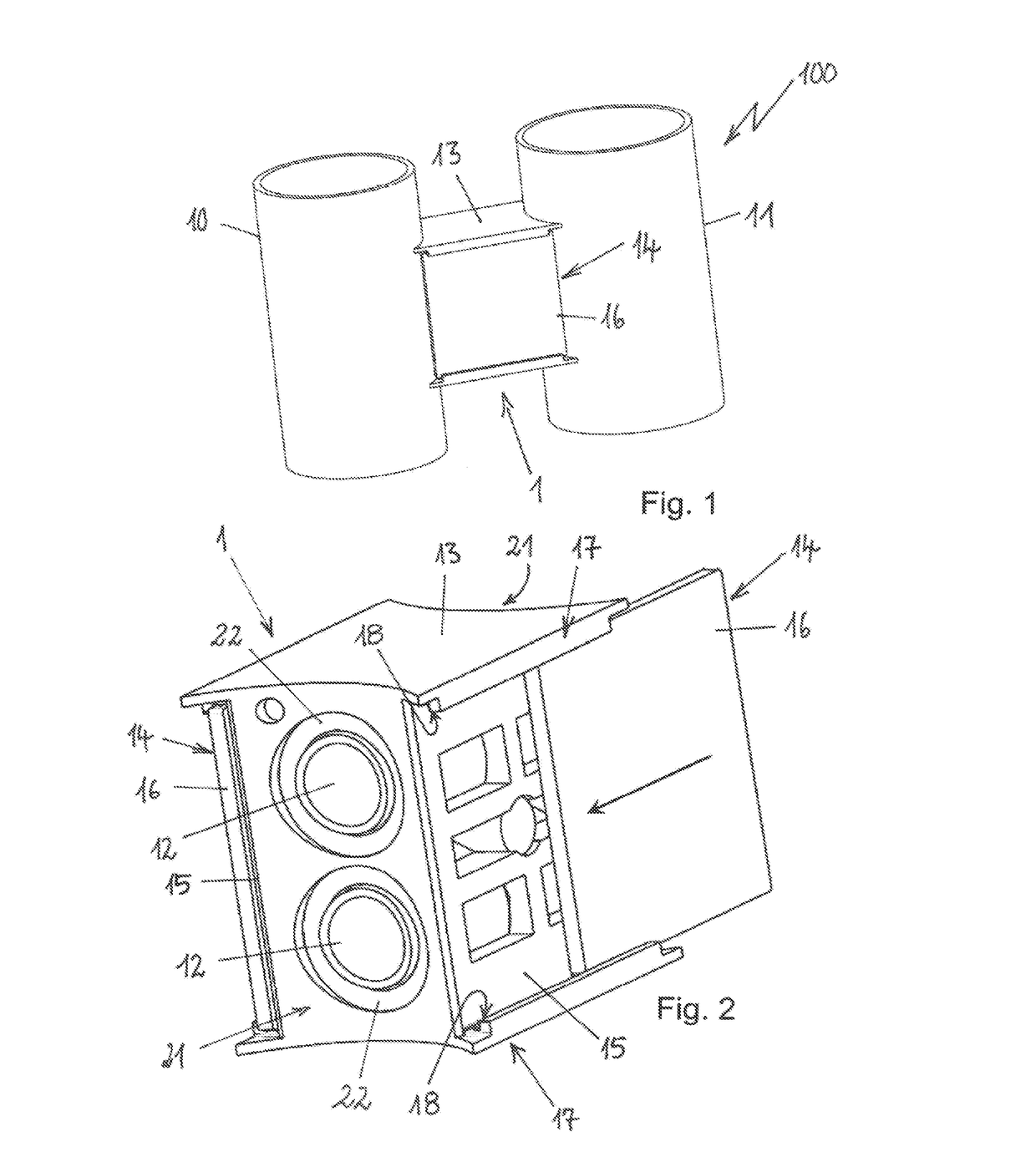
[0023]FIG. 1 a perspective, sectional and schematic view of a vibration damper with a flange according to the invention between a damper tube and a module tube,

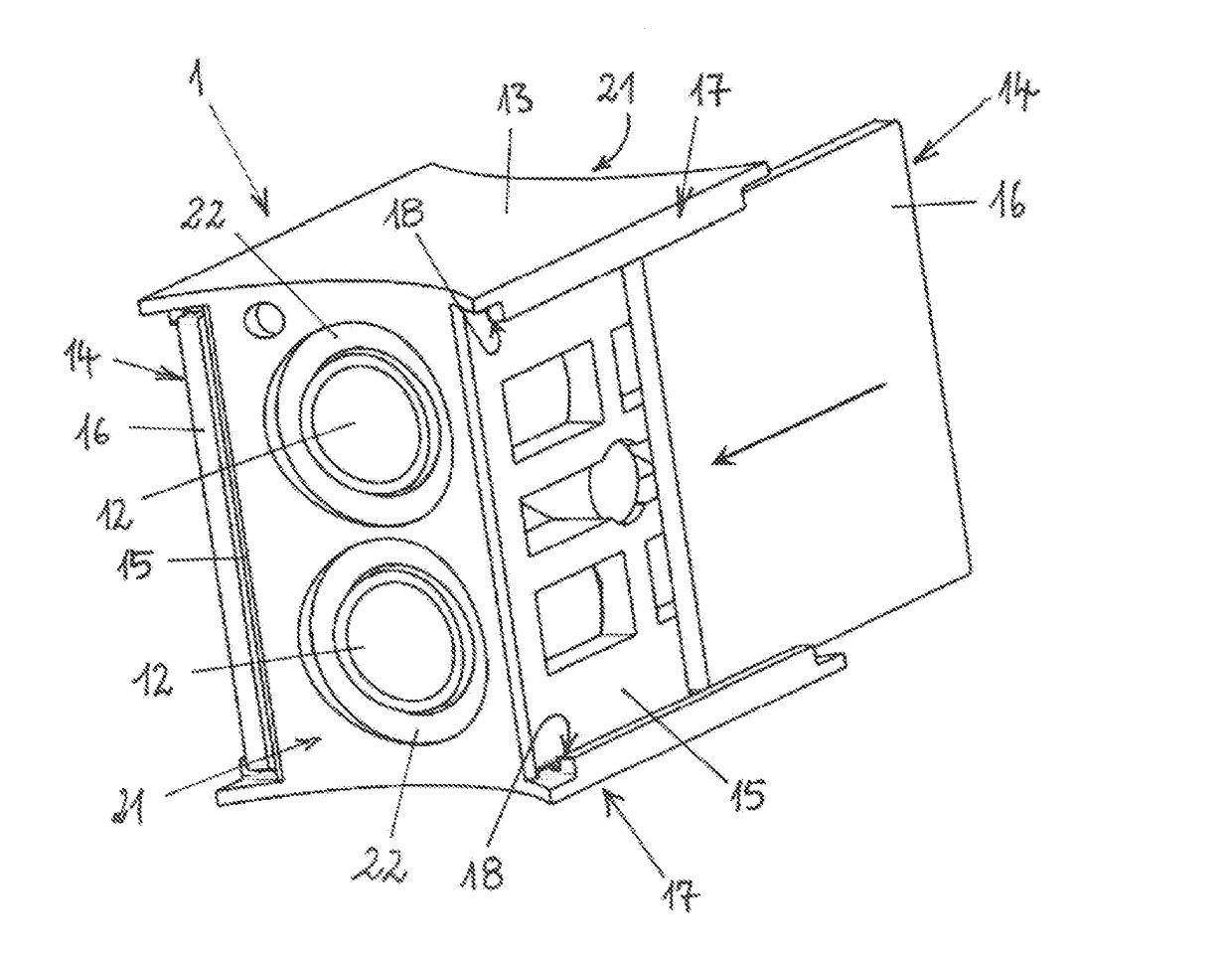
[0024]FIG. 2 a perspective view of a flange with platelike connection elements which are arranged on a plastic and

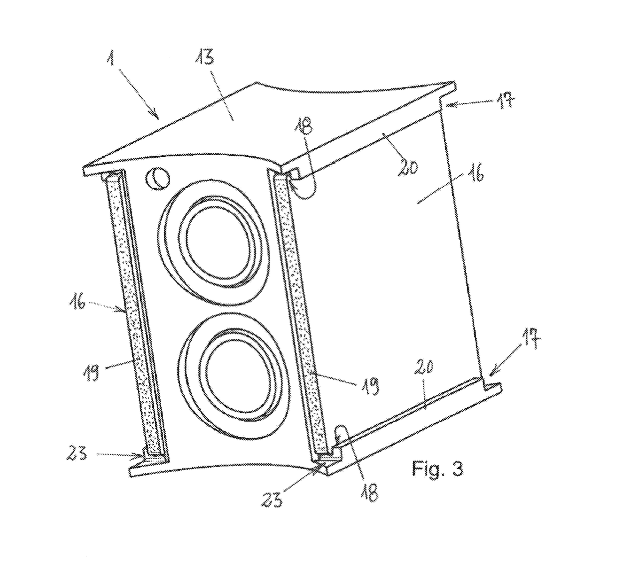
[0025]FIG. 3 a perspective view of the flange in a finished mounted arrangement, and the flange can be fitted in the arrangement shown to a vibration damper tube and to a module tube according to FIG. 1.

[0026]FIG. 1 shows in a perspective view an exemplary embodiment of a vibration damper 100 with a vibration damper tube 10 and an external module tube 11, and between the vibration damper tube 10 and the module tube 11 is arranged a flange 1. The flange 1 joins the module tube 11 to the vibration damper tube ...


PUM


Abstract

A flange for connecting a vibration damper tube to a module tube of a vibration damper may include one or more fluid ducts, by which the module tube is fluidically coupled to the vibration damper tube. The flange may further include a plastic body in which the fluid duct for the fluidic coupling is formed and wherein connection elements are provided that extend between the vibration damper tube and the module tube. The connection elements may form a retaining connection between the vibration damper tube and the module tube. The plastic body may comprise two opposite side walls, and the connection elements may be formed by metal plates arranged on the side walls. The plastic body may also comprise retaining means for the retaining of the plates.”

Description

[0001]The present invention concerns a flange for connecting a vibration damper tube to a module tube of a vibration damper, wherein the flange comprises one or more fluid ducts, by which the module tube is fluidically coupled to the vibration damper tube, wherein a plastic body is provided, in which the fluid ducts for the fluidic coupling is formed, wherein a plastic body is provided, in which the fluid duct for the fluidic coupling is formed and wherein connection elements are provided which extend between the vibration damper tube and the module tube and which form a retaining connection between the vibration damper tube and the module tube. The invention moreover is addressed to a vibration damper with such a flange.PRIOR ART[0002]From DE 11 2007 002 377 T5 there is known a vibration damper with a vibration damper tube and there is provided an external module tube in which an additional valve arrangement is received. The module tube extends perpendicular to the vibration damper...

Claims


Application Information

Patent Timeline
Patent Type & Authority Applications(United States)
IPC IPC(8): F16F9/32
CPCF16F9/325F16F9/3235
Inventor SCHMIDT, KLAUSFRITZ, MICHAEL
Owner THYSSENKRUPP BILSTEIN
Why Eureka
Try Eureka