Display device

a technology for display devices and information, applied in the direction of optical elements, instruments, transportation and packaging, etc., can solve the problems of space saving and design constraints, and achieve the effects of convenient understanding of driving states, effective display of information, and more useful information

Active Publication Date: 2017-04-06
YAZAKI CORP
View PDF5 Cites 45 Cited by
  • Summary
  • Abstract
  • Description
  • Claims
  • Application Information

AI Technical Summary

Benefits of technology

[0020]With the display device configured as described in the above-mentioned item (1), both the projected image and the displayed image can be presented to the occupant. Furthermore, since the first image and the second image are displayed so as to be visually recognized in a state of being arranged side by side, the method of presenting information to the occupant can be changed variously and the information can be displayed effectively. Moreover, even if only the single HUD unit is used, images can be presented to the driver by using two display methods, whereby the display device can produce novelty, stylishness and surprise.
[0022]With the display device configured as described in the above-mentioned item (3), since the display device is implemented as a pair of display devices installed on the left and right sides, the driver can easily understand the driving states of the vehicle and can drive conveniently and safely according to the driving information to be displayed on the left and right display devices.
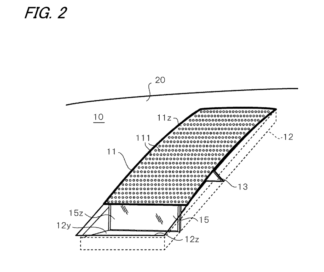
[0023]With the display device configured as described in the above-mentioned item (4), since the display device is installed so as to form part of the surface of the instrument panel without protruding from the surface of the instrument panel, the surface of the instrument panel is smooth, and the design property and the attractive appearance of the instrument panel can be maintained. Moreover, since the display device does not have a member such as a hood for shielding outdoor light, the degree of freedom in design is increased.
[0024]With the display device configured as described in the above-mentioned item (5), since the second display section is covered with the second surface panel so as to be hidden completely, the surface of the instrument panel can be made further smoother and the attractive appearance of the instrument panel can be maintained.

Problems solved by technology

However, in the case that an image different from the image projected by the HUD unit is enabled to be visually recognized by the driver, it is necessary to display the image on a display unit different from the HUD unit, but it is difficult to adopt such a display unit in view of space saving and design.

Method used


Image

  • Display device
  • Display device
  • Display device

Examples


first embodiment

Modification of First Embodiment

[0060]Although the HUD unit is fixed and stationary in the first embodiment, the cover plate of an HUD unit according to a modification of the first embodiment is movable up and down.

[0061]FIG. 6 is a view showing the external appearance of an HUD unit 10A according to the modification. On the front end side (the deep side in the figure) of the cover plate 11A of the HUD unit 10A, a hinge mechanism composed of a rotation shaft 14z pivotally supported on the wall face of the frame 12 in the horizontal direction and protrusion pieces 11m protruding from the front end sections of the cover plate 11A and having hole sections 11y into which the rotation shaft 14z is inserted is provided. When the protrusion pieces 11m are rotated around the rotation shaft 14z, the cover plate 11A performs lift-up operation.

[0062]Furthermore, the second display 15A of the HUD unit 10A is fixed (connected) to the cover plate 11A. When the cover plate 11A performs the lift-up...

second embodiment

Modification 2 of Second Embodiment

[0084]An HUD unit according to modification 2 of the second embodiment has a structure in which the cover plate thereof is foldable in two portions so as to be formed into a valley shape. FIG. 12 is a perspective view showing the external appearance of an HUD unit 10D according to modification 2 of the second embodiment.

[0085]The HUD unit 10D according to modification 2 has a structure almost similar to that according to modification 1, and the cover plate 11D thereof is foldable in two portions so as to be formed into a valley shape. The cover plate 11D is formed of a member being foldable at its central section. When the cover plate 11D is folded so as to be formed into a valley shape, the cover plate 11D2 thereof moves in the depth direction in the figure so as to slide along the peripheral sections of the opening section 12z.

[0086]In this case, unlike the case of modification 1, a first display 13D is disposed on the bottom side of the cover p...


PUM


Abstract

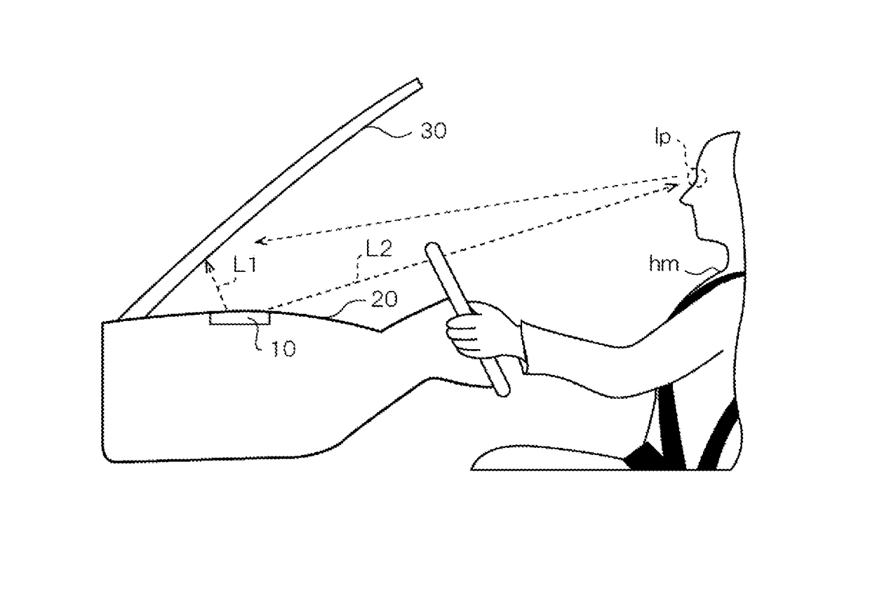
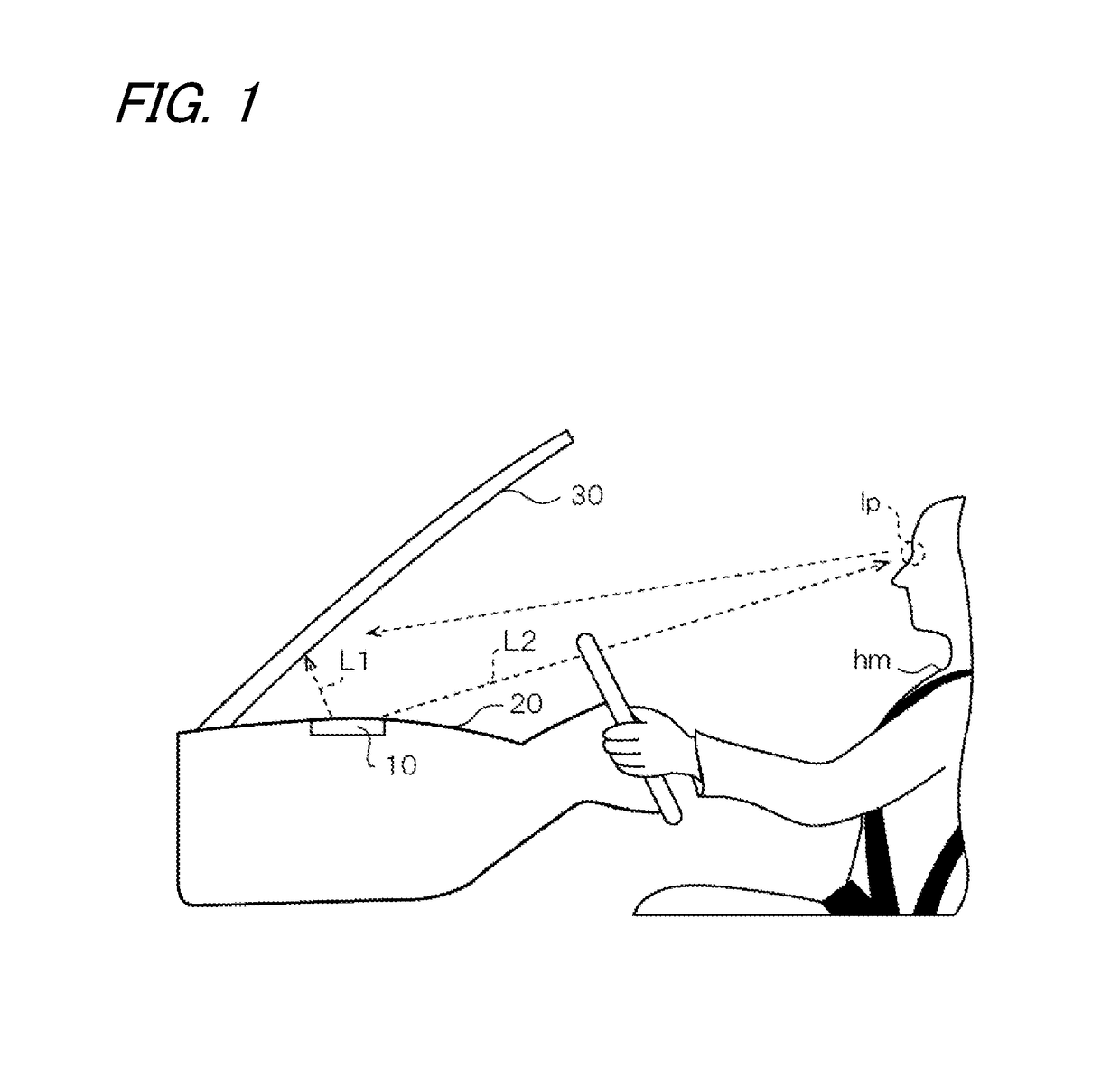
An HUD unit is equipped with a first display and a second display. The light irradiating directions of the first display and the second display are adjusted so that the first image irradiated from the first display, reflected by the front window of a vehicle and visually recognized by the driver of the vehicle and the second image irradiated from the second display to the eye point of the driver and visually recognized by the driver are visually recognized in a state of being arranged side by side.

Description

CROSS REFERENCE TO RELATED APPLICATIONS[0001]This application is based on and claims priority from Japanese patent application No. 2015-198519 filed on Oct. 6, 2015, the entire contents of which are incorporated herein by reference.BACKGROUND OF THE INVENTION[0002]1. Technical Field[0003]The present invention relates to a display device for displaying information.[0004]2. Background Art[0005]Conventionally, head-up display (HUD) units for projecting images onto the front window of a vehicle have been known as devices for displaying images around the sight line of the driver of the vehicle (refer to Patent Document JP-A-2011-105306). Furthermore, HUD units having a combiner and being used to project images onto the combiner have also been known (refer to Patent Document JP-A-2015-104930).SUMMARY[0006]In the case of such a conventional HUD unit, an image is projected onto the front window or the combiner, and the image projected onto the front window or the combiner is visually recogn...

Claims


Application Information

Patent Timeline
Patent Type & Authority Applications(United States)
IPC IPC(8): G02B27/01B60K35/00
CPCG02B27/0101B60K35/00B60K2350/92G02B27/0149B60K2350/2052G02B2027/0132G02B27/01B60K2370/152B60K37/00B60K37/02G02B2027/0154B60K2370/154B60K2370/339B60K2370/28B60K2370/1529B60K2370/785B60K2370/334B60K2370/70
Inventor TAKAMATSU, MASAHIRONAGATA, MASAHIDEKANAI, TAKAO
Owner YAZAKI CORP
Why Eureka
Try Eureka