Sealed battery

a sealed battery and sealing technology, applied in the direction of batteries, cell components, cell component details, etc., can solve the problems of short use period (durable period) set for a sealed battery, the safety mechanism is imposed on the load, and the safety mechanism may be reduced in working pressure and/or weld strength, etc., to achieve the effect of reducing the working pressure of the safety mechanism and reducing the strength of the weld

Active Publication Date: 2017-04-06
TOYOTA JIDOSHA KK
View PDF0 Cites 6 Cited by
  • Summary
  • Abstract
  • Description
  • Claims
  • Application Information

AI Technical Summary

Benefits of technology

[0007]When the battery internal pressure rises to a certain degree of internal pressure, however, a load is imposed on the safety mechanism, such as the above-described current-interrupting valve and explosion-proof valve, or an airtightly-welded location between a main container and a lid member constituting a battery container, even if these valves do not operate. As a result, there is a concern that the safety mechanism may be reduced in working pressure and / or the weld strength may be reduced because of long-term use. Therefore, the period of use (durable period) set for a sealed battery is short.
[0008]The present invention was therefore made to solve the problem, and has an object to provide a sealed battery having a structure capable of preventing reduction in working pressure of a safety mechanism and / or reduction in weld strength.

Problems solved by technology

When the battery internal pressure rises to a certain degree of internal pressure, however, a load is imposed on the safety mechanism, such as the above-described current-interrupting valve and explosion-proof valve, or an airtightly-welded location between a main container and a lid member constituting a battery container, even if these valves do not operate.
As a result, there is a concern that the safety mechanism may be reduced in working pressure and / or the weld strength may be reduced because of long-term use.
Therefore, the period of use (durable period) set for a sealed battery is short.

Method used


Image

  • Sealed battery
  • Sealed battery
  • Sealed battery

Examples


embodiment

tery 100

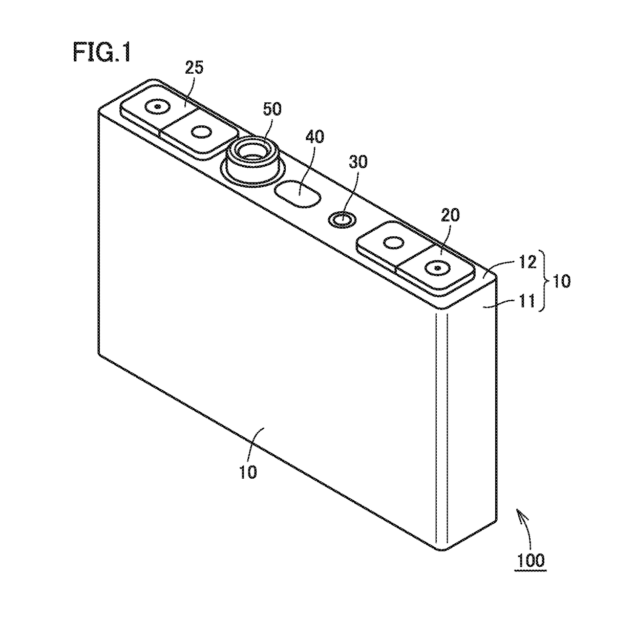
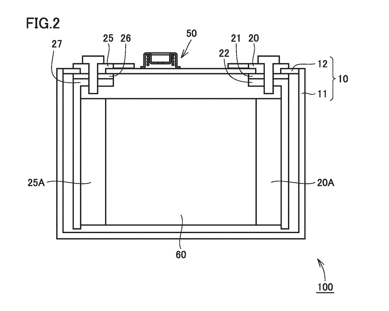
[0020]Referring to FIGS. 1 and 2, the structure of a sealed battery 100 according to an embodiment will be described. FIG. 1 is a perspective view showing the appearance of sealed battery 100, and FIG. 2 is a cross sectional view showing the internal structure of sealed battery 100.

[0021]Referring to FIG. 1, sealed battery 100 is a sealed battery with a battery element housed in a sealed casing 10. Casing 10 includes a container body 11 and a lid member 12. Aluminum or the like is used for each of container body 11 and lid member 12. Lid member 12 is bonded airtightly to container body 11 by way of weld-bonding or the like.

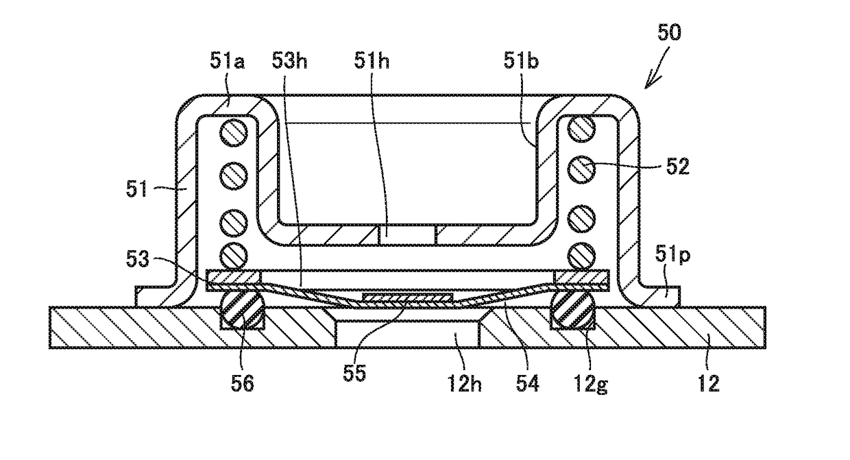
[0022]Lid member 12 is provided with an anode terminal 20, a cathode terminal 25, an infusion plug 30, an explosion-proof valve 40, and a valve 50. An electrolyte is introduced into casing 10 through infusion plug 30. Explosion-proof valve 40 has a function of becoming cracked when the internal pressure of casing 10 rises to a predetermined internal pressu...


PUM

PropertyMeasurementUnit
thicknessaaaaaaaaaa
outer diameteraaaaaaaaaa

Abstract

A sealed battery with a battery element housed in a sealed casing. The sealed battery includes a valve brought into a closed state when a pressure of a gas in the casing is less than a first pressure P1, into an open state when the pressure is more than or equal to the first pressure P1 and less than a second pressure P2, and into the closed state when the pressure is more than or equal to the second pressure P2, and a safety mechanism configured to, when the internal pressure reaches a third pressure P3 exceeding the second pressure P2, operate in accordance with the third pressure P3.

Description

[0001]This nonprovisional application is based on Japanese Patent Application No. 2015-197580 filed on Oct. 5, 2015 with the Japan Patent Office, the entire contents of which are hereby incorporated by reference.BACKGROUND OF THE INVENTION[0002]Field of the Invention[0003]The present invention relates to a structure of a sealed battery.[0004]Description of the Background Art[0005]A sealed battery including a battery element in a sealed casing is disclosed in Japanese Patent Laying-Open No. 2001-185113.[0006]Japanese Patent Laying-Open No. 2001-185113 points out that an issue will arise in that when a battery is used as an in-vehicle battery which will be used for long years, the battery internal pressure is increased by gas generation in the battery through charging / discharging or use in high-temperature environments. Employed as a solution therefor is a safety mechanism such as a current-interrupting valve for interrupting a current path when the battery internal pressure rises to ...

Claims


Application Information

Patent Timeline
Patent Type & Authority Applications(United States)
IPC IPC(8): H01M2/12H01M2/34H01M2/02H01M10/0525H01M50/103
CPCH01M2/1229H01M10/0525H01M2220/20H01M2/024H01M2/345H01M50/317H01M50/325H01M50/333H01M50/103H01M2200/20Y02E60/10H01M50/383H01M50/578
Inventor UMEYAMA, HIROYAIMANISHI, HIROAKI
Owner TOYOTA JIDOSHA KK
Why Eureka
Try Eureka