Paper delivery device

a technology of paper delivery and paper forming apparatus, which is applied in the directions of transportation and packaging, electrographic process, instruments, etc., can solve the problem of not being able to downsize the image forming apparatus having the functions of both mechanisms, and achieve the effect of preventing the generation of nip marks

Inactive Publication Date: 2017-04-13
MURATA MASCH LTD
View PDF9 Cites 4 Cited by
  • Summary
  • Abstract
  • Description
  • Claims
  • Application Information

AI Technical Summary

Benefits of technology

[0020]With such an operation, during the movement of the shift frame in the second direction, the paper is not brought into a curved state due to nipping by three rollers. Accordingly, it is possible to prevent the generation of nip marks on the paper during the movement of the paper in the second direction.
[0021]Thus, with preferred embodiments of the present invention, a mechanism that performs a shift sorting function and the mechanism that performs a decurling function are housed in the paper delivery device of the image forming apparatus in a compact manner.

Problems solved by technology

As a result, it has been impossible to downsize the image forming apparatus having functions of both mechanisms.

Method used


Image

  • Paper delivery device
  • Paper delivery device
  • Paper delivery device

Examples


first preferred embodiment

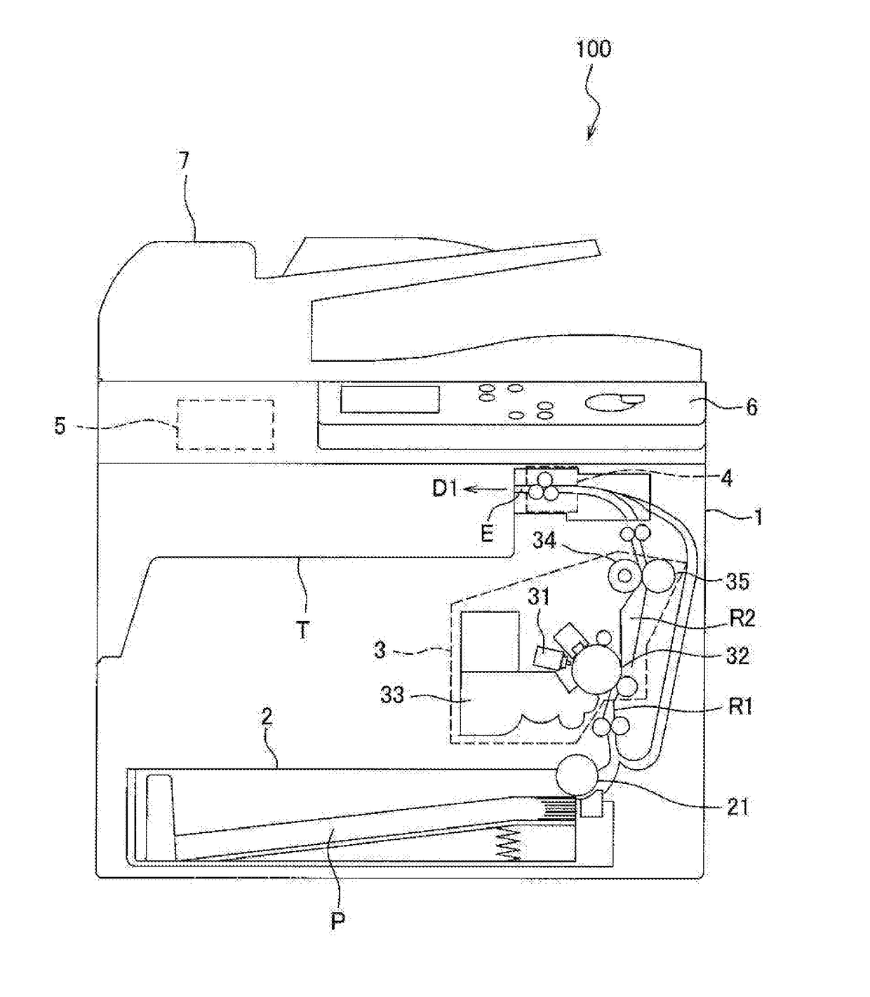
[0036]Hereinafter, an image forming apparatus according to a first preferred embodiment of the present invention is described. First, the overall configuration of the image forming apparatus 100 according to the first preferred embodiment is described with reference to FIG. 1.

[0037]The image forming apparatus 100 includes a body 1. The body 1 defines a body of the image forming apparatus 100. A paper exit tray T is provided on a portion of the body 1. A paper P transported by a paper delivery device 4 (described later) is delivered to the paper exit tray T.

[0038]The image forming apparatus 100 includes a paper feed cassette 2. The paper feed cassette 2 is disposed on a lower portion of the body 1 (below an image former 3). Papers P to be transported to the image former 3 for formation of an image are placed in the paper feed cassette 2. The papers P placed on the paper feed cassette 2 are transported to a first transportation path R1 due to the rotation of a pickup roller 21.

[0039]T...


PUM

PropertyMeasurementUnit
rotationaaaaaaaaaa
distanceaaaaaaaaaa
timeaaaaaaaaaa

Abstract

A paper delivery device includes a shift frame movable in a second direction perpendicular or substantially perpendicular to a first direction along which paper is delivered to outside, a driver that moves the shift frame in the second direction, a drive roller with a first outer peripheral surface extending in the second direction and supported by the shift frame such that the drive roller is rotatable about a first shaft parallel or substantially parallel to the second direction, a first driven roller with a second outer peripheral surface extending in the second direction and contactable with the first outer peripheral surface at a first contact position, the first driven roller supported by the shift frame such that the first driven roller is rotatable about a second shaft parallel or substantially parallel to the second direction following the rotation of the drive roller, the first driven roller being rotated in a state where the paper is nipped between the first outer peripheral surface and the second outer peripheral surface thus transporting the paper in the first direction, and a second driven roller with a third outer peripheral surface extending in the second direction and contactable with the first outer peripheral surface at a second contact position downstream of the first contact position in the first direction, the second driven roller being supported by the shift frame such that the second driven roller is rotated about a third shaft disposed parallel or substantially parallel to the second direction following the rotation of the drive roller, the second driven roller being rotated in a state where the paper which is nipped between the first outer peripheral surface and the second outer peripheral surface is nipped by the first outer peripheral surface and the third outer peripheral surface thus transporting the paper in the first direction.

Description

CROSS-REFERENCE TO RELATED APPLICATIONS[0001]This application claims priority under 35 U.S.C. 119 to Japanese Patent Application No. 2015-202239 filed on Oct. 13, 2015, which application is hereby incorporated by reference in its entirety.BACKGROUND OF THE INVENTION[0002]1. Field of the Invention[0003]The present invention relates to a paper delivery device provided in an image forming apparatus for forming an image on a paper and delivers the paper on which the image is formed to the outside.[0004]2. Description of the Related Art[0005]Conventionally, there has been known an image forming apparatus which delivers papers on which images are formed to a paper exit tray while sorting the papers in accordance with the number of copies. For example, there has been known an image forming apparatus equipped with a shift frame which is slidable back and forth in a roller axis direction of a paper delivery roller.[0006]In this image forming apparatus, the shift frame is moved in the directi...

Claims


Application Information

Patent Timeline
Patent Type & Authority Applications(United States)
IPC IPC(8): G03G15/00B65H7/00B65H9/10B65H5/06
CPCG03G15/6529B65H5/062B65H2801/06B65H9/10B65H2404/732B65H7/00B65H29/125B65H29/14B65H33/08B65H43/00B65H2301/36B65H2301/4212B65H2301/42192B65H2301/512565B65H2404/1422B65H2404/1424B65H2511/20B65H2701/1313B65H2801/27G03G2215/00662G03G15/6576B65H2220/01B65H2220/02B65H2220/11B65H2301/3613B65H29/70
Inventor KAMEDA, TSUYOSHI
Owner MURATA MASCH LTD
Why Eureka
Try Eureka