Image sensor and imaging device

Active Publication Date: 2017-04-13
OLYMPUS CORP
View PDF5 Cites 5 Cited by
  • Summary
  • Abstract
  • Description
  • Claims
  • Application Information

AI Technical Summary

Benefits of technology

[0008]The present invention is achieved in view of such a situation, and aims to provide an image sensor and an imaging

Problems solved by technology

However, when the position of a photographing lens is significantly deviated from the focusing position, that is, in a largely-defocused state (also called a largely blurred state), the brightness pattern of a subject image is not clear and a defocus amount cannot be detected.
In particular, this problem is more frequently caused for a fast photographing lens having a small aperture F-value.
However, in t

Method used


Image

  • Image sensor and imaging device
  • Image sensor and imaging device
  • Image sensor and imaging device

Examples


Example

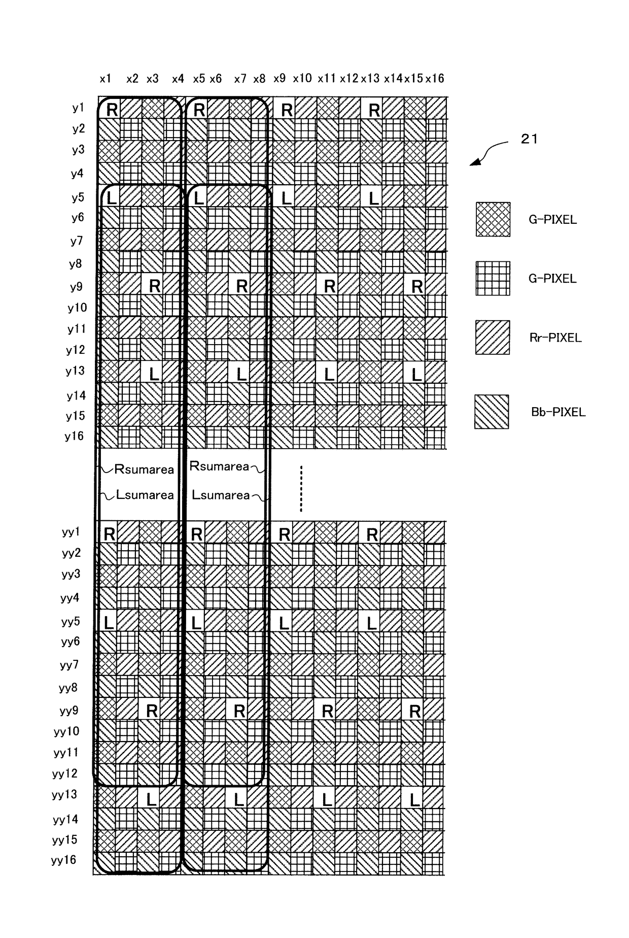
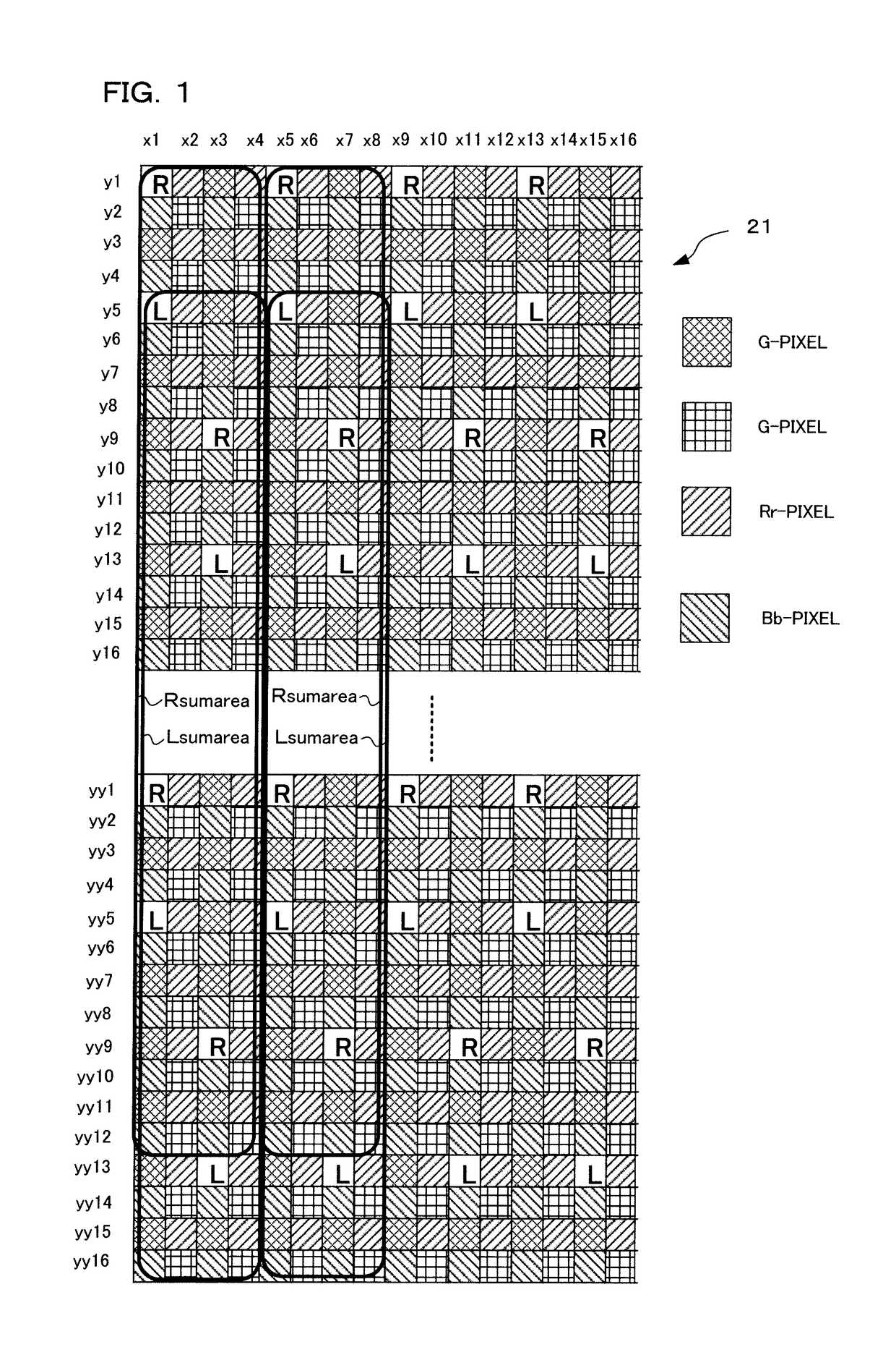
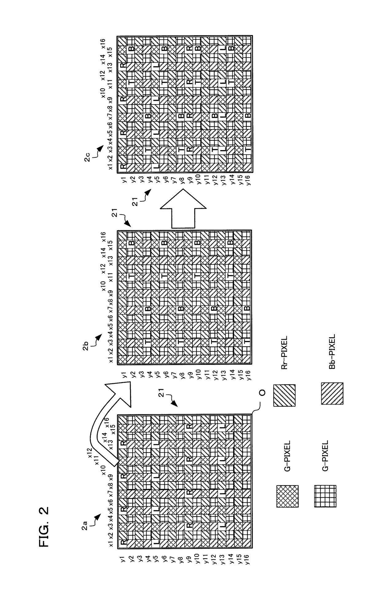
[0020]Hereinafter, there will be explained an example of application to an image sensor as an embodiment of the present invention. In an outline, the image sensor according to the present embodiment has an image plane phase difference AF function of a pixel light-shielding type, and horizontal pixel lines (RL-pixel lines) are arranged at an interval not smaller than four pixel pitches (in detail, refer to FIG. 1 and the like) and further vertical pixel lines (TB-pixel lines) are arranged also at an interval not smaller than four pixel pitches. The TB-pixel lines are arranged at the interval obtained by rotating the RL-pixel lines by just 90 degrees (in detail, refer to 2b in FIG. 2).

[0021]Further, focus detecting pixels arranged at the positions of pixels other than G-pixels (refer to Bb-pixels or Rr-pixels shown in FIGS. 1 to 3E, for example), have two or more different kinds of light shielding ratios (in detail, refer to FIGS. 3A to 3E, FIGS. 4A and 4B, and the like). Out of the t...


PUM


Abstract

An image sensor comprising a plurality of imaging pixels, a plurality of focus detecting pixels in which opening positions of light receiving sections are shifted from those of the imaging pixels, and a plurality of color filters arranged corresponding to the imaging pixels and the focus detecting pixels, wherein first focus detecting pixels in which opening positions are shifted in a first direction are arranged at positions corresponding to first color filters of the imaging pixels, and second focus detecting pixels in which opening positions are shifted in the first direction and which have opening ratios different from those of the first focus detecting pixels are arranged at positions corresponding to the first color filters.

Description

CROSS-REFERENCE TO RELATED APPLICATIONS[0001]This application is a Continuation Application of PCT Application No. PCT / JP2015 / 059036, filed on Mar. 25, 2015 and based upon and claiming the benefit of priority from prior Japanese Patent Application No. 2014-129326, filed on Jun. 24, 2014, the entire contents of all of which are incorporated herein by reference.BACKGROUND OF THE INVENTION[0002]1. Field of the Invention[0003]The present invention relates to an image sensor in which focus detecting pixels are arranged on an imaging plane for performing focus detection by a phase difference method, and to an imaging device including this image sensor.[0004]2. Description of the Related Art[0005]There is conventionally known an image sensor in which focus detecting pixels are arranged at a part of the image sensor for performing focus detection by a phase difference method. For example, Japanese Patent Laid-Open No. 2013-257494(hereafter referred to as “Patent Literature 1”) discloses an ...

Claims


Application Information

Patent Timeline
IPC IPC(8): H04N5/369H04N9/04H01L27/146H04N5/378
CPCH04N5/3696H01L27/14621H04N9/045H04N5/378H01L27/14623H01L27/14645G02B5/201H04N23/672H04N25/704H04N25/134H04N25/75G02B7/34
Inventor KIKUCHI, TETSUOOKAZAWA, ATSURO
Owner OLYMPUS CORP
Why Eureka
Try Eureka