Bicycle handlebar

a technology for bicycles and handlebars, applied in the direction of bicycle equipment, steering devices, transportation and packaging, etc., can solve the problems of waste of materials, increase weight, thick wall thickness of materials, etc., and achieve the effect of preserving strength and rigidity, and reducing weigh

Active Publication Date: 2017-04-20
MARUI SHINJI
View PDF16 Cites 1 Cited by
  • Summary
  • Abstract
  • Description
  • Claims
  • Application Information

AI Technical Summary

Benefits of technology

[0026]The handlebar according to the present invention has a reduced weight while preserving strength and rigidity when the handlebar is secured to a plurality of stems.

Problems solved by technology

However, because a conventional handlebar is manufactured without discriminating between the locations where strength, stiffness or durability is and is not required, the wall thickness of the material is thick even at locations that do not require strength, stiffness or durability, which wastes material and adds weight.

Method used


Image

  • Bicycle handlebar
  • Bicycle handlebar
  • Bicycle handlebar

Examples


Embodiment Construction

[0036]Preferred embodiments according to the present invention will be described in detail below, referencing the drawings. Note that the scope of the present invention is not limited to the embodiments or drawings set forth below, but rather may be altered and modified in many ways.

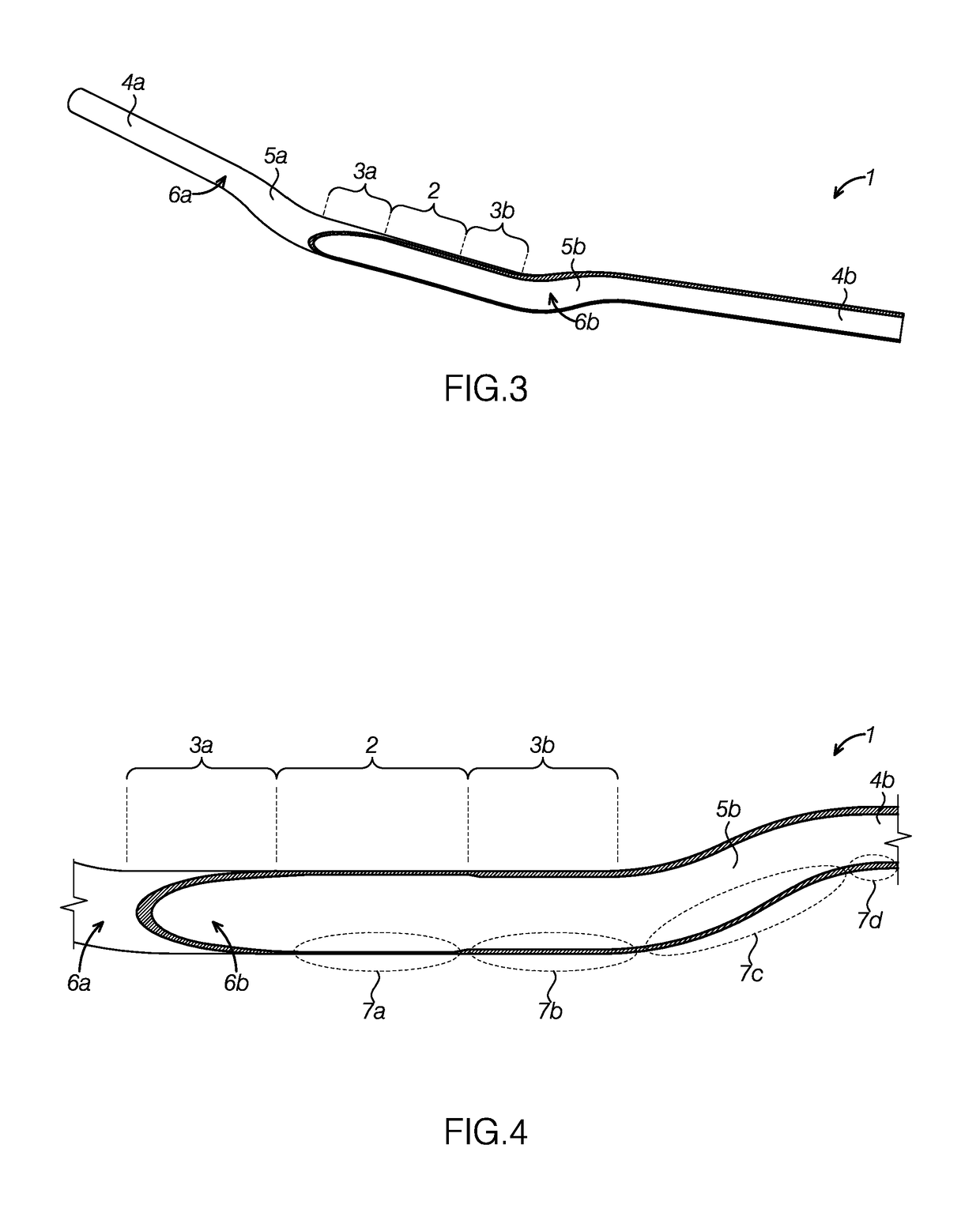
[0037]FIG. 3 illustrates a first preferred embodiment of a handlebar apparatus, or simply handlebar, 1 configured to be attached to stems at two locations. As illustrated in FIG. 3, the handlebar 1 comprises a center portion 2, stem attaching portions 3a and 3b, grip portions 4a and 4b, and bent portions 5a and 5b, where the bent portions 5a and 5b are provided so as to elevate the grip portions 4a and 4b when attached to the stem. While a particular shape for the handlebar 1 is shown, including bent portions 5a and 5b, the present invention may include handlebars of various shapes, with or without bent portions 5a and 5b, or with bent portions 5a and 5b having various and different bends formed therein....


PUM


Abstract

A lightweight handlebar configured to be coupled to a plurality of stems is characterized by the strength of the center portion not being a maximum. Moreover, the design may be such that a single handlebar is attached between two stems, wherein the strength at a center portion that is positioned between stem attaching positions is less than the strength of the portions that are positioned toward the outsides of the stem attaching portions. Moreover, a marker for indicating unsuitability for securing to a stem may be provided at the center portion of the handlebar.

Description

BACKGROUND OF THE INVENTION[0001]1. Field of the Invention[0002]The invention relates generally to bicycle handlebars.[0003]2. Description of Prior Art and Related Information[0004]FIG. 1 shows a conventional handle structure in a typical bicycle. As illustrated in FIG. 1, in the typical handle structure two fork legs 108, on the left and the right, having a mechanism for steering while supporting the axle of a front wheel 114, are connected by a fork crown 113 above the front wheel 114. Given this, the upper portion of the fork crown 113 is connected to a single steering column, or steering tube, 111. Additionally, the top end of the steering column 111 is connected to the handlebar 100, at a center portion 102, through a connecting component of a stem 109.[0005]Moreover, the steering column 111 is borne rotatably in a front frame 17 through a head tube 10 of a front frame 17 (structured from a head tube 10, a top tube 15, and a down tube 16). Moreover, the axle of the front wheel ...

Claims


Application Information

Patent Timeline
Patent Type & Authority Applications(United States)
IPC IPC(8): B62K21/12
CPCB62K21/12B62K21/18
Inventor MARUI, SHINJI
Owner MARUI SHINJI
Why Eureka
Try Eureka