Sensor Fusion for Implement Position Estimation and Control

a technology of position estimation and sensor fusion, which is applied in the field of work machines, can solve the problems of insufficient arc of the implement to use a rotary sensor for accurate arm angle measurements, and the sensor can be difficult to calibrate and maintain in a construction or excavation environment,

Active Publication Date: 2017-04-20
CATERPILLAR INC
View PDF2 Cites 24 Cited by
  • Summary
  • Abstract
  • Description
  • Claims
  • Application Information

AI Technical Summary

Benefits of technology

[0005]In another aspect of the disclosure, a system for positioning an implement includes an implement moveably attached to a chassis of the machine, a hydraulic circuit configured to supply pressurized hydraulic fluid, and a hydraulic cylinder that moves the implement relative to the chassis via hydraulic fluid flow in the hydraulic circuit. The system also includes a sensor configured to generate data corresponding to the hydraulic fluid flow in the hydraulic circuit. The system further includes an implement inertial measurement unit (IMU) that generates implement position information about a position of the implement relative to gravity and a chassis IMU that provides machine position information about a position of the chassis machine relative to gravity. The system further includes a controller configured to control a position of the implement relative to the chassis based on an estimated position of the implement relative to the chassis. The estimated position of the implement relative to the chassis is calculated using a weighted combination of the hydraulic fluid flow, the implement position information from the implement IMU, and the machine position information from the chassis IMU.

Problems solved by technology

Cylinder position sensors using magnetostrictive technology can give accurate measurements of implement position but can be expensive and may require each cylinder rod to be gun bored so that wiring and magnetic sensors can be mounted inside.
In addition to the cost, these sensors can be difficult to calibrate and maintain in a construction or excavation environment.
An inertial measurement unit (IMU) can give a relatively accurate position in an ideal environment but are susceptible to noise when used with heavy equipment.
Some implements, such as a dozer blade on arms, do not swing a large enough arc to use a rotary sensor for accurate measurements of arm angle.
However, the '534 patent fails to account for other movement of the machine or inaccuracies associated with cylinder position estimation.

Method used


Image

  • Sensor Fusion for Implement Position Estimation and Control
  • Sensor Fusion for Implement Position Estimation and Control
  • Sensor Fusion for Implement Position Estimation and Control

Examples


Embodiment Construction

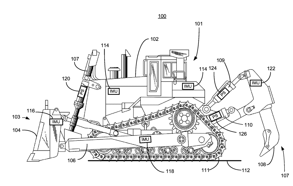
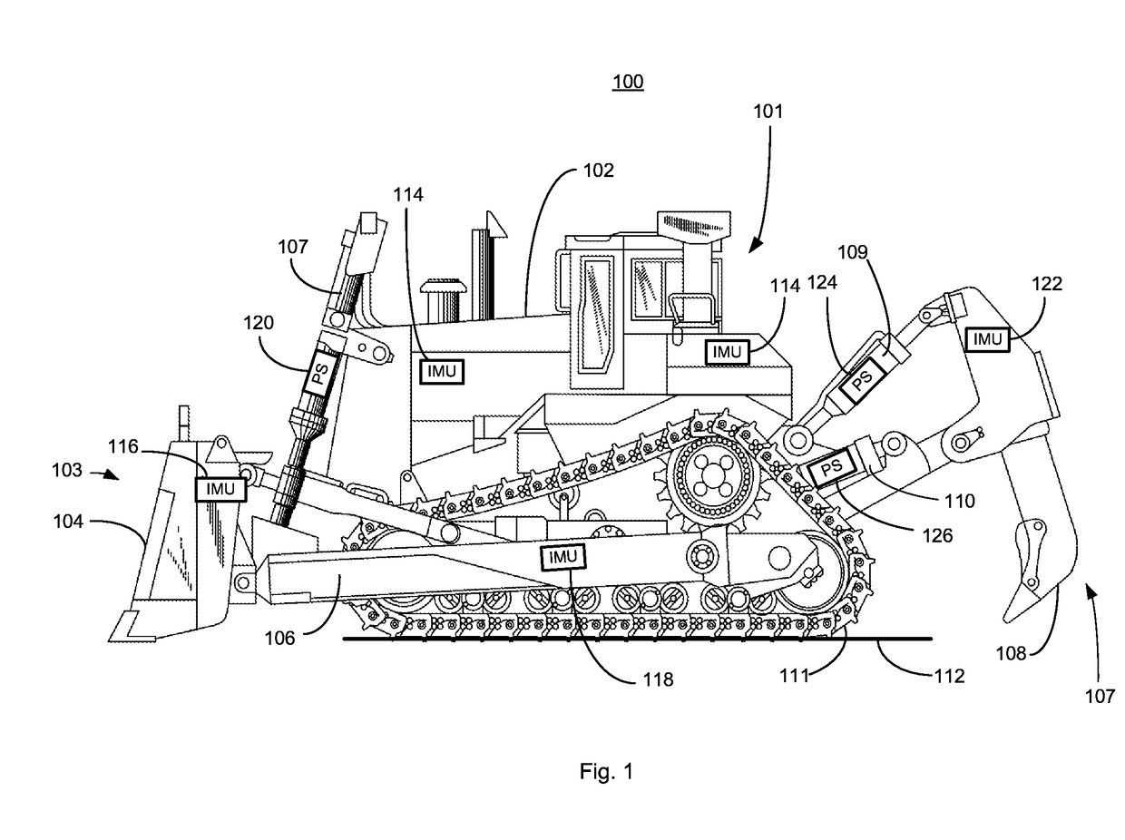
[0016]Referring to FIG. 1, a machine 100 such as a dozer 101 is used to illustrate an exemplary embodiment of sensor fusion for implement position estimation. Of course, the machine 100 can be presented in the form of many other earth-moving work machines including but not limited to excavators, motor graders, pipelayers, loaders, pavers, harvesters, mining trucks, and the like. The dozer 101 includes a chassis 102 and an implement 103. One embodiment of the implement 103 is a blade 104. The blade 104 is coupled to an arm 106 which is raised and lowered via a cylinder 107. The dozer 101 may also have another implement, a ripper 108. The ripper 108 is operated by an upper cylinder 109 and a lower cylinder 110. The dozer 101 has tracks 111 that engage a work surface 112 to propel the dozer 101.

[0017]Inertial measurement units (IMUs) are devices that report acceleration in one or more dimensions or degrees of freedom. A time derivative of acceleration data can used to provide velocity ...


PUM


Abstract

A controller uses a Kalman filter to develop an estimated position of an implement based on a previous implement position, an implement pitch, an implement pitch rate and an estimated implement linkage velocity. The controller moves the implement to a desired position based on the estimated position of the implement.

Description

TECHNICAL FIELD[0001]The present disclosure is generally directed to a work machine and, more particularly, to operation of a hydraulic accessory of a work machine.BACKGROUND[0002]Large machines, such as dozers, scrapers, excavators, etc., use implements to perform various work functions. Accurately positioning an implement, for example, the depth of a ripper or blade, may be important to the accurate preparation of a worksite for subsequent activity, including mining or construction. Cylinder position sensors using magnetostrictive technology can give accurate measurements of implement position but can be expensive and may require each cylinder rod to be gun bored so that wiring and magnetic sensors can be mounted inside. In addition to the cost, these sensors can be difficult to calibrate and maintain in a construction or excavation environment. An inertial measurement unit (IMU) can give a relatively accurate position in an ideal environment but are susceptible to noise when used...

Claims


Application Information

Patent Timeline
Patent Type & Authority Applications(United States)
IPC IPC(8): E02F9/26
CPCE02F9/264E02F9/265E02F3/845E02F3/847E02F9/2029
Inventor FAIVRE, JOSEPH L.KRONE, BRADLEY P.KRAUSE, STEVEN R.
Owner CATERPILLAR INC
Why Eureka
Try Eureka