Hydraulic cylinder cover

a technology of hydraulic cylinders and cylinder rods, applied in fluid-pressure actuators, soil-shifting machines/dredgers, building repairs, etc., can solve problems such as damage to the extended piston rod, exposure to falling work materials such as debris,

Active Publication Date: 2017-04-20
CATERPILLAR WORK TOOLS
View PDF14 Cites 3 Cited by
  • Summary
  • Abstract
  • Description
  • Claims
  • Application Information

AI Technical Summary

Problems solved by technology

During work the piston rod may be extended form the cylinder barrel and may be exposed to falling work material such as debris.
In particular, during demolition work the falling debris may damage the extended piston rod.

Method used


Image

  • Hydraulic cylinder cover
  • Hydraulic cylinder cover
  • Hydraulic cylinder cover

Examples


Embodiment Construction

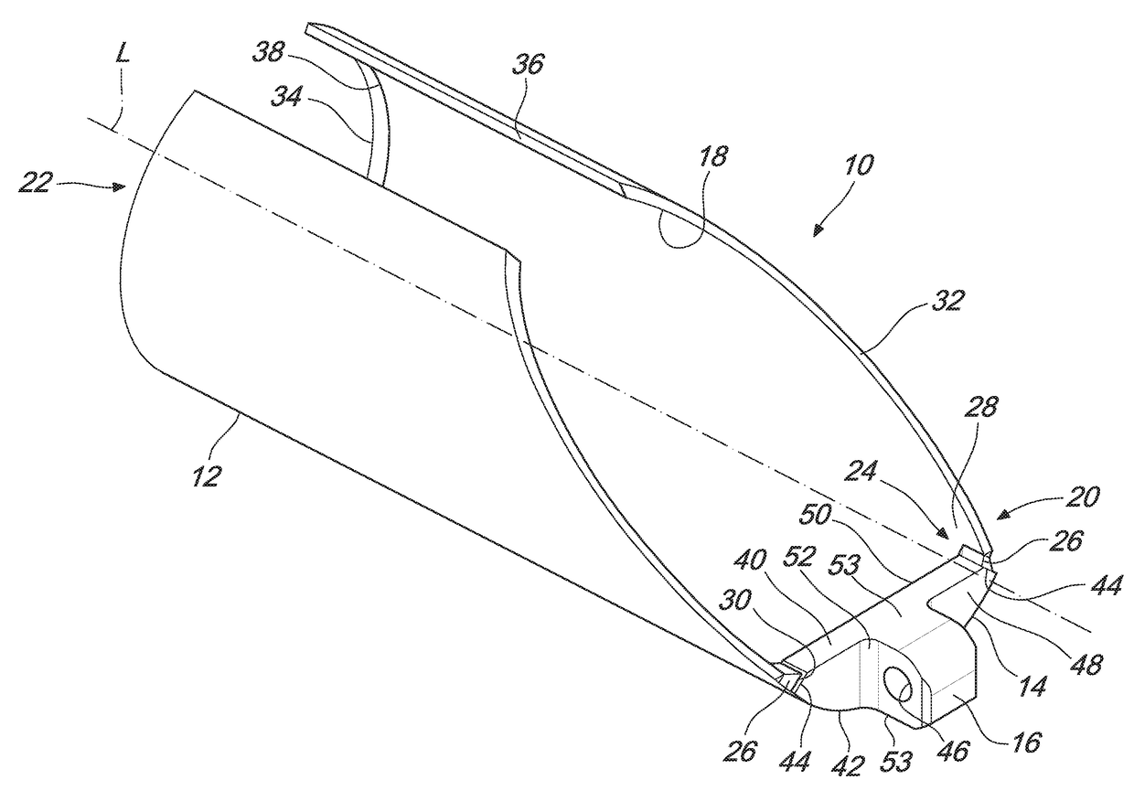
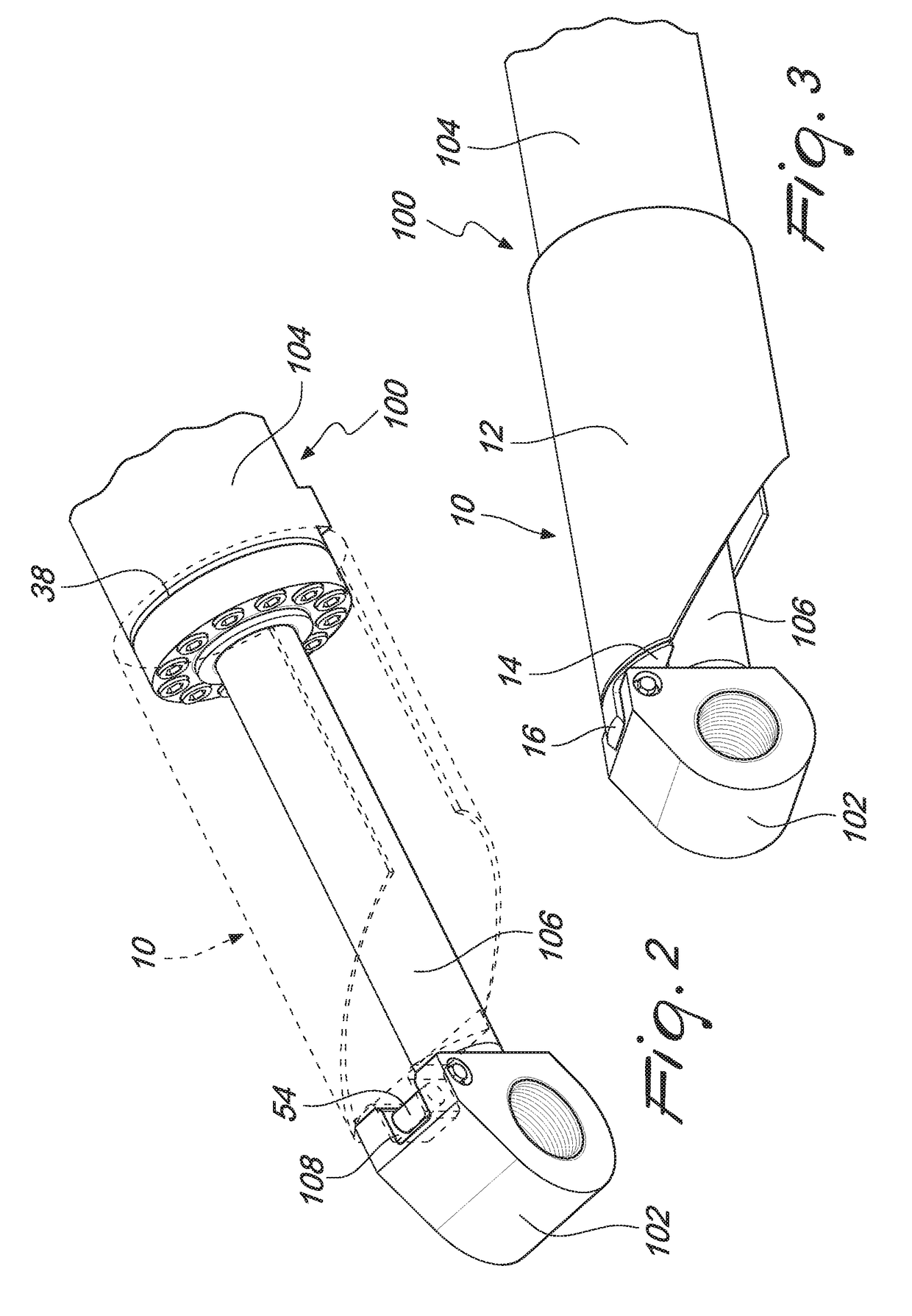
[0012]This disclosure generally relates to a hydraulic cylinder cover 10 for assembly onto a hydraulic cylinder provided in a machine tool. FIG. 1 illustrates a hydraulic cylinder cover 10. The hydraulic cylinder cover 10 may comprise a body 12, a flange 14 and a cover eye 16.

[0013]The body 12 may be provided in a form of tube. Body 12 may be extended along a longitudinal axis L. Body 12 may have a lumen 18. The lumen 18 may be configured to accommodate a cylinder barrel of a hydraulic cylinder (not shown). Body 12 may slidably accommodate the cylinder barrel of the hydraulic cylinder. Body 12 has an inner surface 28. In an embodiment, the inner surface 28 may be curved. A portion of the inner surface 28 may slidably contact cylinder barrel.

[0014]Body 12 has a first end 20 and a second end 22. The flange 14 may be coupled to the first end 20 of the body 12. The flange 14 may be welded to the body 12 at the first end 20. Flange 14 may be coupled at a tip of the first end 20.

[0015]Fir...


PUM


Abstract

A hydraulic cylinder cover is disclosed. The hydraulic cylinder cover may have a body having a first end and a second end. The hydraulic cylinder cover may also have a flange positioned at the first end. In addition, the hydraulic cylinder cover may have a cover eye provided on the flange. The cover eye may be configured to connect to a piston rod eye of a hydraulic cylinder.

Description

TECHNICAL FIELD[0001]This disclosure relates to the field of hydraulic cylinders and in particular to hydraulic cylinders used in construction and / or demolition tools.BACKGROUND[0002]Hydraulic cylinders may be used in construction equipment, manufacturing machinery, and civil engineering. Hydraulic cylinders may provide unidirectional force through a unidirectional stroke.[0003]Hydraulic cylinders may have a piston rod that may be formed of a hard cold-rolled steel. The piston rod may be attached to a piston and may extend from the cylinder barrel through the rod-end head. The piston rod may connect the hydraulic actuator to the machine tool for performing work. The piston rod may have piston rod eyes for connection to the machine tool.[0004]During work the piston rod may be extended form the cylinder barrel and may be exposed to falling work material such as debris. In particular, during demolition work the falling debris may damage the extended piston rod. Hydraulic cylinder cover...

Claims


Application Information

Patent Timeline
Patent Type & Authority Applications(United States)
IPC IPC(8): F15B15/14E02F9/22
CPCF15B15/1457E04G23/082E02F3/965E02F9/2271F15B15/1438F15B2215/30F15B15/1423F15B2211/8606F15B2211/865
Inventor VAN GEMERT, JOHANNES LAMBERT LEONARDUS
Owner CATERPILLAR WORK TOOLS
Why Eureka
Try Eureka