Wireless charging lamp

a charging lamp and wireless technology, applied in the field of illumination devices, can solve the problems of only obtaining power for charging products, affecting the normal application of digital products, and electric appliances not being able to achieve the charging function,

Active Publication Date: 2017-04-20
DONGGUAN TONGCHENG IND
View PDF10 Cites 2 Cited by
  • Summary
  • Abstract
  • Description
  • Claims
  • Application Information

AI Technical Summary

Benefits of technology

[0007]An object of the present invention is to overcome the disadvantages mentioned above and provide a wireless charging lamp which has not only the conventional lighting function but also the wireless charging function.
[0027]3) The wireless charging lamp of the present invention is simple to use, easy to operate and has a wide range of application. In addition, the wireless charging lamp of the present invention has novelty and innovation for meeting the demand and development of the markets, and thus has strong competitiveness in the markets.
[0028]4) The charging receiver can be equipped with various adapters for different digital products, so as to preventing the consumers from purchasing multiple charging receivers, which not only provides convenience for the consumers but also saves the cost of consumption.

Problems solved by technology

However, the conventional lamps have a single function and are only capable of providing a simple function of lighting.
The disadvantage of the wired connection charging is that digital products must be connected to the power supply through the data line while charging and the charging is restricted by the connection of the data line, which affects normal applications of the digital products.
In the wireless charging technologies on the current market, charging products can only obtain power and complete charging by being provided on an electromagnetic field contact surface or a specified point formed by a specified charging module.
Although no additional data lines are required, electric appliances are not capable of achieving the charging function until contacting the electromagnetic field contact surface or the specified point.
The digital products can not be operated during the charging process.

Method used


Image

  • Wireless charging lamp
  • Wireless charging lamp
  • Wireless charging lamp

Examples


embodiment 1

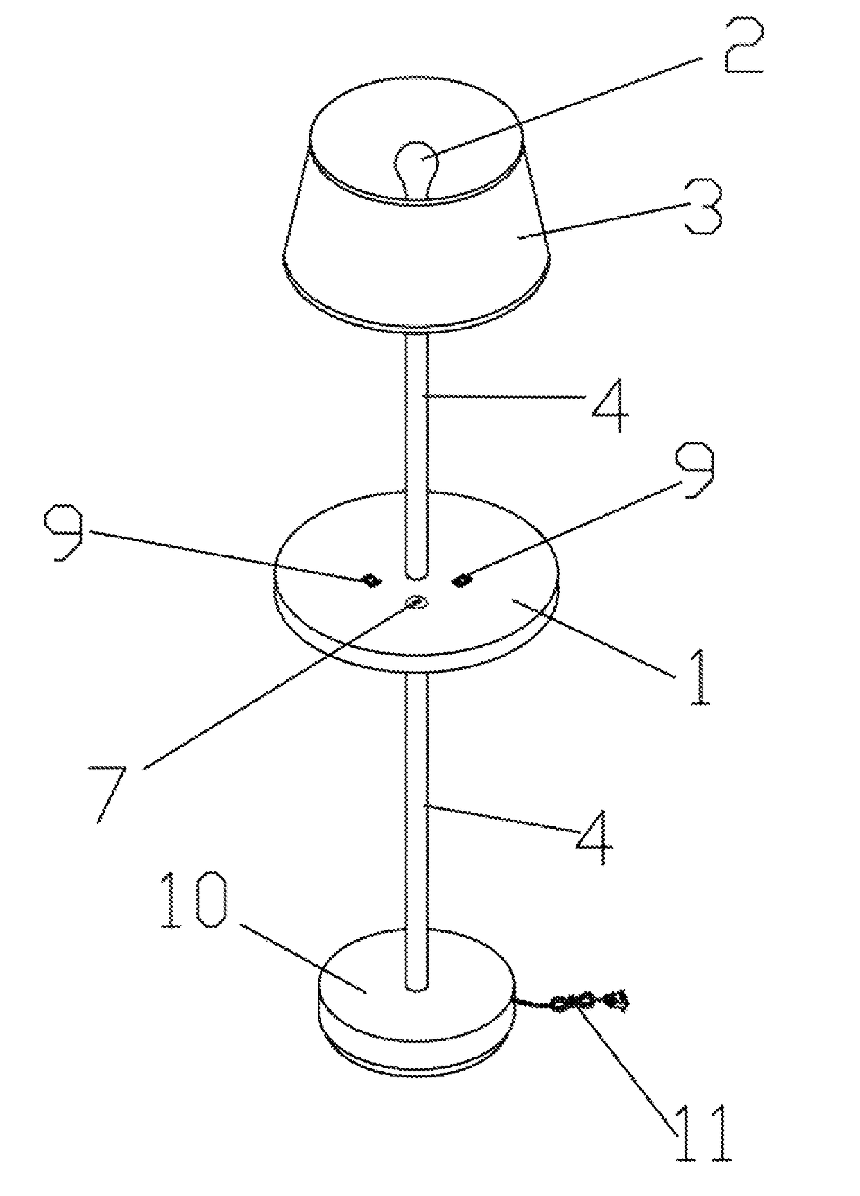
[0040]Referring to FIGS. 1-5, according to an embodiment 1 of the present invention, a wireless charging lamp comprises:

[0041]a lamp holder 1, a light source 2, a lampshade 3 and a supporting part 4;

[0042]wherein the light source 2 is provided in the lampshade 3, and the supporting part 4 is for connecting the lamp holder 1 and the light source 2, and in the embodiment 1, the lamp is a table lamp; and

[0043]the supporting part 4 is a cylinder structure capable of being bended, an upper end of the supporting part is connected with the lampshade 3, and a lower end of the supporting part 4 is connected with a top surface of the lamp holder 1, in such a manner that the lampshade 3 is capable of swinging in a random direction with the supporting part 4.

[0044]In the embodiment 1, the lamp holder 1 has a flat cylindrical structure, a master control circuit board is provided in the lamp holder 1, a power plug 11 for powering the light source 2 is connected with the master control circuit boa...

embodiment 2

[0048]Referring to FIG. 6, compared with the Embodiment 1, Embodiment 2 has structural differences as follows. A clamp 22 for clamping a table is provided on a bottom surface of the lamp holder 1. A top surface of the clamp 22 is fixed on the bottom surface of the lamp holder 1. In the embodiment 2, the lamp is a clamp lamp. While in use, the clamp 22 can be directly clamped to an edge or other positions of the table. The installation is stable and easy to operate. An emitter sign 7 is provided on a side surface of the lamp holder 1, so as to facilitate a user to understand and identify a specific position of the charging emitter.

embodiment 3

[0049]Referring to FIG. 7, compared with the Embodiment 1, Embodiment 3 has structural differences as follows. The lamp is a wall lamp. The lamp holder 1 comprises a wall holder and a dish cover. The dish cover is fixedly covered on an opening of the wall holder. The wall holder is vertically provided. A bottom surface of the wall holder has a location hole for being fixedly installed on a wall. An emitter sign 7 is provided on a side surface of the lamp holder 1, so as to facilitate a user to understand and identify a specific position of the charging emitter. The supporting part 4 is formed by a reversed U-shaped metal bracket. A first end of the reversed U-shaped metal bracket is fixedly provided on an external surface of the dish cover, and a second end of the reversed U-shaped metal bracket is connected with the lampshade 3. In the FIG. 7, three lampshades are provided. A cross bar 8 is connected on the second end of the reversed U-shaped metal bracket. The three lampshades are...


PUM


Abstract

A wireless charging lamp belonging to the technical field of an illumination device comprises: a lamp holder, a light source, a lampshade and a supporting part. A master control circuit board and a charging emitter are provided in the lamp holder. The wireless charging lamp further comprises a charging receiver which is independently equipped, wherein the charging receiver comprises a charging receiver shell a receiving circuit board provided in the charging receiver shell. The wireless charging lamp not only has a traditional lighting function but also a wireless charging function. Compared with the conventional structures, the structure of the present invention needs neither a data line nor contacting with the digital product to achieve a charging function. The charging emitter is provided inside the lamp holder. Inserting the charging receiver into a charging interface of the digital product is capable of automatically activate the charging function.

Description

CROSS REFERENCE OF RELATED APPLICATION[0001]The present application claims priority under 35 U.S.C. 119(a-d) to CN 201621131002.5, filed Oct. 18, 2016.BACKGROUND OF THE PRESENT INVENTION[0002]Field of Invention[0003]The present invention relates to the technical field of an illumination device, particularly to a lamp, and more particularly to a wireless charging lamp.[0004]Description of Related Arts[0005]Lamp, which is a kind of household appliance utilized in people's lives for lighting, is an indispensable tool for lighting and learning at night. However, the conventional lamps have a single function and are only capable of providing a simple function of lighting.[0006]In addition, in the conventional arts, there are two ways for charging digital products. The first one is the commonly used wired connection charging which needs to connect a data line while charging. The advantage of the wired connection charging is that the charging efficiency thereof is high and the current is s...

Claims


Application Information

Patent Timeline
Patent Type & Authority Applications(United States)
IPC IPC(8): F21V33/00F21V21/02F21V21/088H02J7/02F21V1/00
CPCF21V33/00H02J7/025F21V21/02F21V21/088F21V1/00F21S6/002F21S6/005F21S8/033H02J7/0042H02J50/20
Inventor LI, MING
Owner DONGGUAN TONGCHENG IND
Why Eureka
Try Eureka