Ergonomic capacitance pen

Inactive Publication Date: 2017-04-20
WALTOP INT
View PDF3 Cites 8 Cited by
  • Summary
  • Abstract
  • Description
  • Claims
  • Application Information

AI Technical Summary

Benefits of technology

[0007]In view of the foregoing, one object of the present invention is to provide an ergonomic capacitance pen for solving the drawbacks of the conventional capacitance pen. By changing where the battery is put in the ergonomic capacitance pen, the gravity center of the ergonomic capacitance pen is moved to the head portion (or the front portion or the lower portion) of the ergonomic capacitance pen. Therefore, the ergonomic capacitance pen can have a structure having best proportion of allocation for easily holding the ergonomic capacitance pen, and it is comfortable and suitable for long-time using without the pain of the hand.
[0008]According to one of the objects above, an ergonomic capacitance pen is disclosed herein. The ergonomic capacitance pen comprises an electrical signal transmitting module and a housing. The electrical signal transmitting module is deposited inside the housing for emitting an electrical signal to a touch panel device (such as touch panel, touch screen phone, tablet PC, etc.). The electrical signal transmi

Problems solved by technology

It increases the burden of hand when people use the conventional capacitance pen 100 and thereby it causes pain of the hand after using the conventiona

Method used


Image

  • Ergonomic capacitance pen
  • Ergonomic capacitance pen
  • Ergonomic capacitance pen

Examples


Embodiment Construction

[0014]The detailed description of the present invention will be discussed in the following embodiments, which are not intended to limit the scope of the present invention, but can be adapted for other applications. While drawings are illustrated in details, it is appreciated that the quantity of the disclosed components may be greater or less than that disclosed, except expressly restricting the amount of the components. Although specific embodiments have been illustrated and described, it will be appreciated by those skilled in the art that various modifications may be made without departing from the scope of the present invention, which is intended to be limited solely by the appended claims.

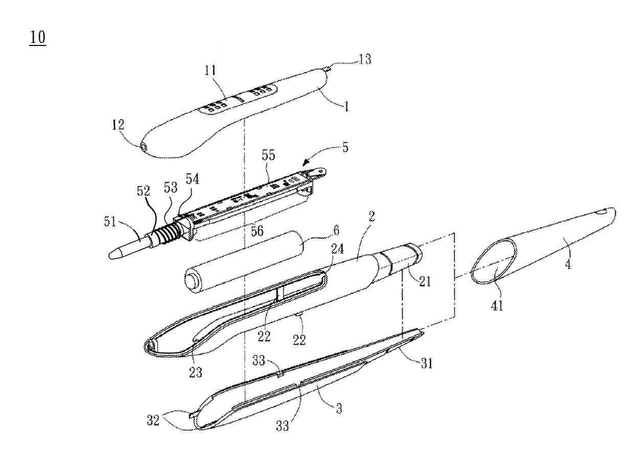
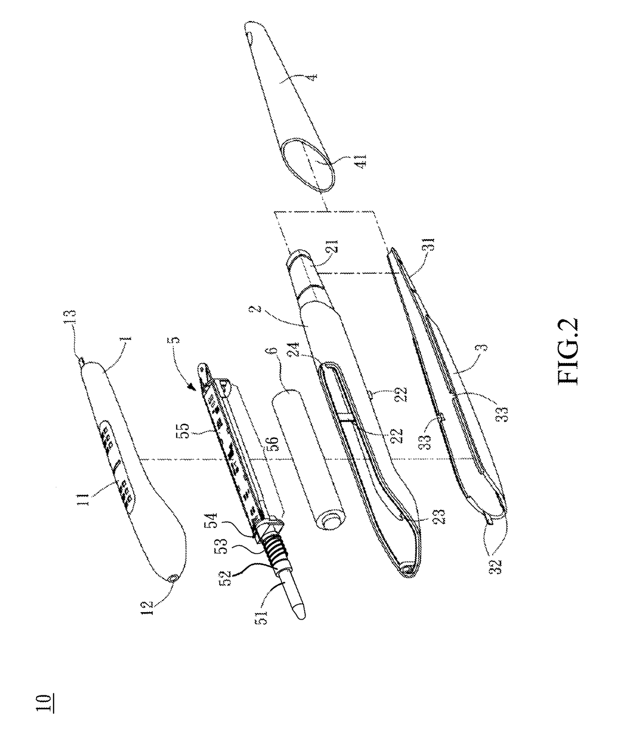
[0015]Please refer to FIG. 2 and FIG. 3 simultaneously, FIG. 2 is an explosion drawing illustrating an ergonomic capacitance pen 10 in accordance with one embodiment of the present invention, and FIG. 3 is a drawing illustrating the ergonomic capacitance pen 10 in accordance with one embodimen...


PUM


Abstract

The present invention relates to an ergonomic capacitance pen. The ergonomic capacitance pen comprises an electrical signal transmitting module and a housing. The electrical signal transmitting module is deposited inside the housing. The electrical signal transmitting module comprises a core, a core holder, a spring, a sensor holder, a circuit board, and a battery holder. The battery holder is deposited on one surface of the circuit board and they are parallel with each other. When a battery is put into the battery holder, the battery and the circuit board are parallel with each other. Therefore, the gravity center of the ergonomic capacitance pen moves to the position near the head of the ergonomic capacitance pen, and the ergonomic capacitance pen can have a structure having best proportion of allocation for easily holding the ergonomic capacitance pen.

Description

CROSS REFERENCE[0001]This application claims priority from Taiwan Patent Application No. 104134035, filed Oct. 16, 2015, the content of which are hereby incorporated by reference in their entirety for all purposes.BACKGROUND OF THE INVENTION[0002]1. Field of the Invention[0003]The present invention relates to an ergonomic capacitance pen, and particularly relates to an ergonomic capacitance pen which can have a structure having best proportion of allocation for easily holding the ergonomic capacitance pen by moving the gravity center of the ergonomic capacitance pen.[0004]2. Description of the Prior Art[0005]Along with popularization of touch devices, capacitance pens have been widely used to handwriting input (means input information by handwriting) to different touch devices (such as touch panel, touch screen phone, tablet PC, etc.).Referring to FIG. 1, it illustrates a conventional capacitance pen 100, and the back portion of the conventional capacitance pen 100 is in perspective...

Claims


Application Information

Patent Timeline
IPC IPC(8): G06F3/0354G06F3/044G06F3/038
CPCG06F3/03545G06F3/044G06F3/0383G06F3/0442B43K24/00
Inventor MAO, CHUNG-FUUHO, HSIN-CHIANG
Owner WALTOP INT
Why Eureka
Try Eureka