Absolute Robot-Assisted Positioning Method

a robot-assisted positioning and robot technology, applied in the direction of manipulators, instruments, process and machine control, etc., to achieve the effect of simplifying the initialisation of the facility

Active Publication Date: 2017-04-27
FFT PRODIONSSYST
View PDF4 Cites 69 Cited by
  • Summary
  • Abstract
  • Description
  • Claims
  • Application Information

AI Technical Summary

Benefits of technology

[0029]The facility can be initialised for the first time automatically by means of the computer. The initialisation is automated using measuremen

Problems solved by technology

If errors occur during assembly, or if parts of the assembly task are changed,

Method used


Image

  • Absolute Robot-Assisted Positioning Method
  • Absolute Robot-Assisted Positioning Method
  • Absolute Robot-Assisted Positioning Method

Examples


Embodiment Construction

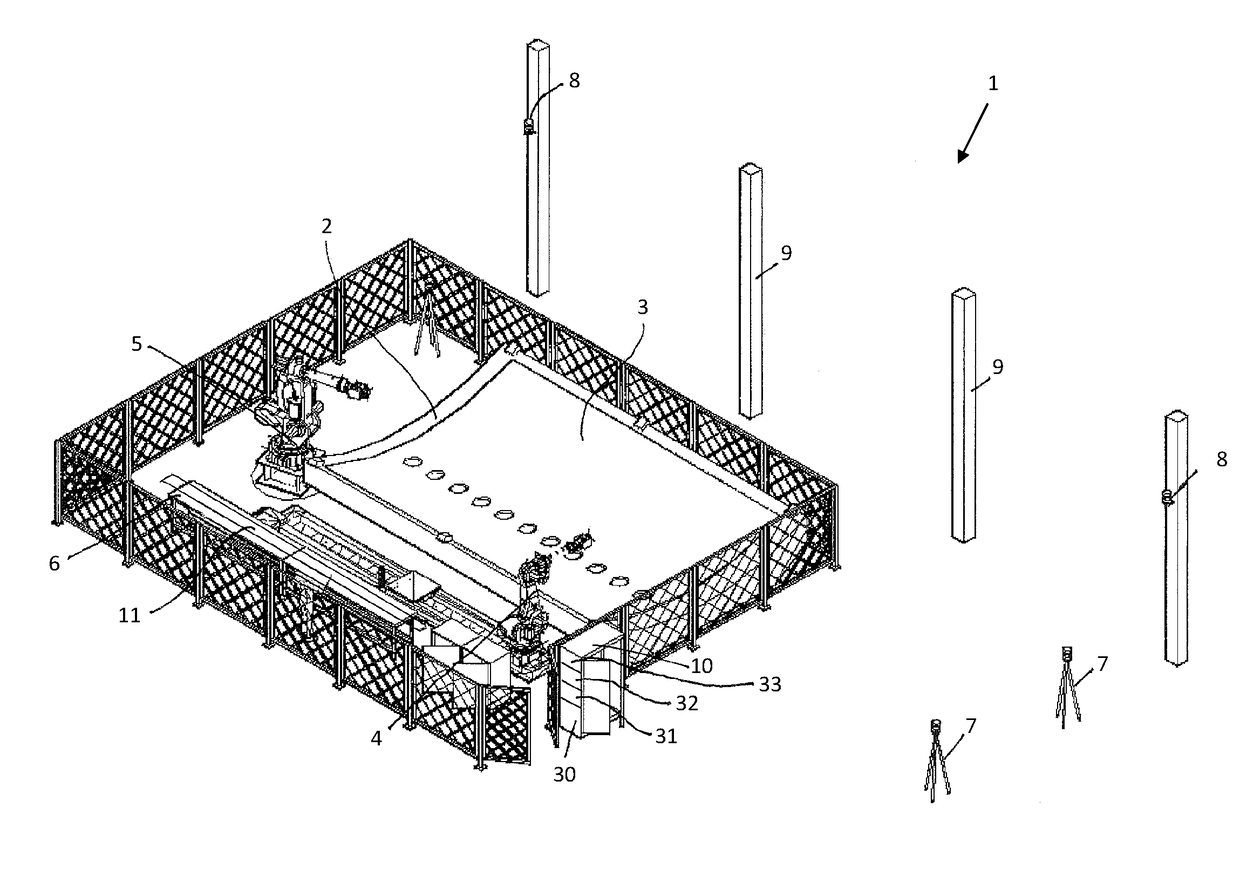
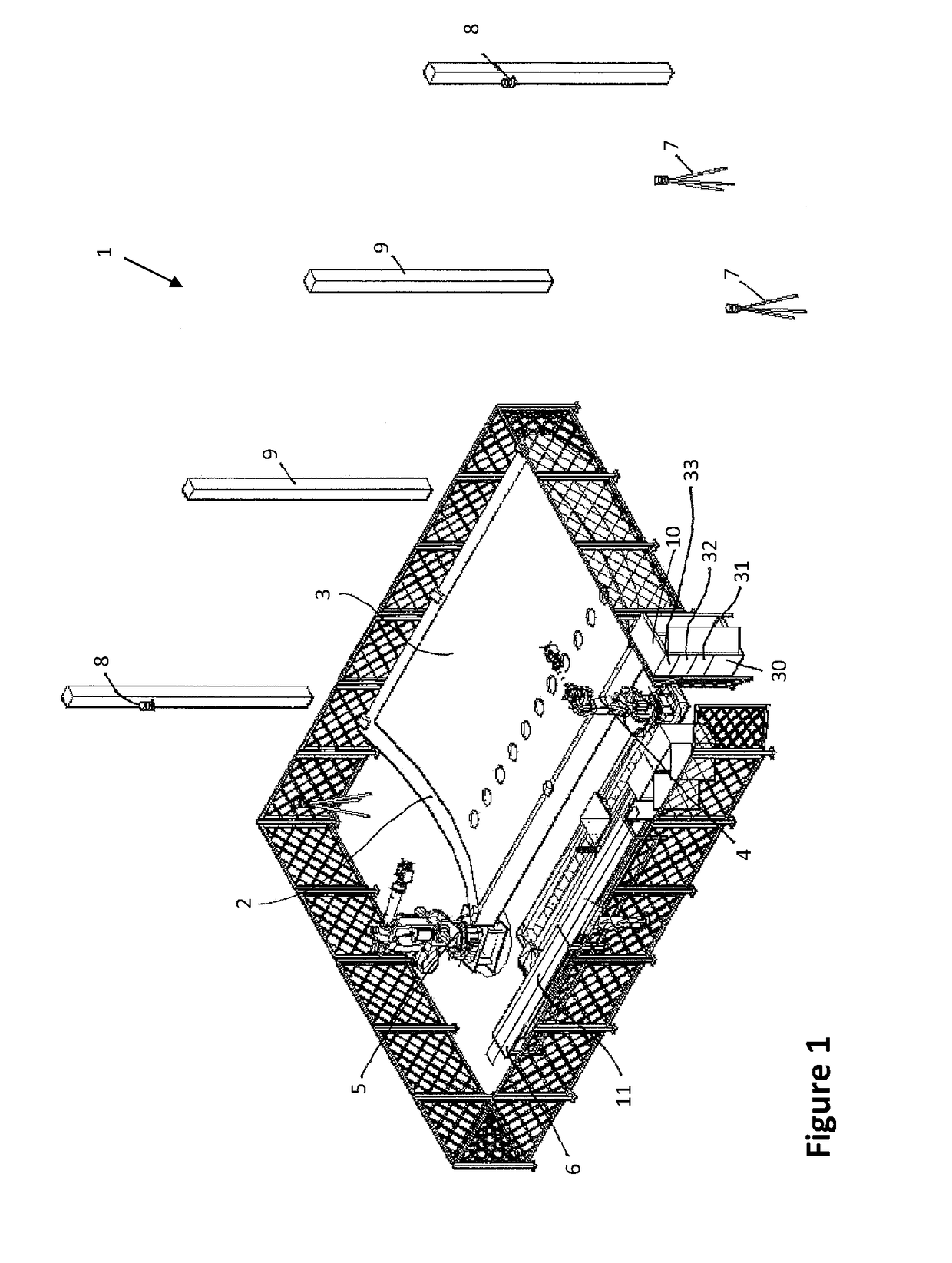
[0057]FIG. 1 shows a facility 1, comprising: a tool 2 on which a large-area sub-assembly 3—in this case, a part of an aircraft shell—lies; two robots 4, 5; and a depository 6. The facility 1 also comprises: a measurement system, which consists of the measurement systems 7, 8 and 9; and a computer 10.

[0058]The sub-assembly 3 is a part of an outer shell of an aircraft fuselage which is to be reinforced with ribs or stringers 11. A first rib 11, which has been placed on the depository 6 by other robots which are not shown, can be gripped and placed on the sub-assembly 3 by the robots 4, 5. It has to be placed or positioned on the sub-assembly 3 with absolute precision.

[0059]In order for this to be possible, the facility 1 comprises multiple measurement systems 7, 8, 9 which monitor the movements—i.e. a direction of the movement, a speed of the movement, a distance travelled during the movement, a torque, a pressure force and other parameters—of the robots. The measurement systems 7, 8,...


PUM


Abstract

An absolute robot-assisted positioning method is provided which can be performed by a facility. The method optimises an assembly task which has been created theoretically at a computer workstation and which is implemented in reality by the facility. The disclosed facility includes at least one robot, at least one measurement system and a computer, wherein the at least one measurement system monitors the at least one robot while the assembly task is being performed, and the robot and the measurement system are connected to each other via the computer.

Description

BACKGROUND[0001]1. Technical Field[0002]The invention relates to an absolute robot-assisted positioning method which can be performed by a facility. The method optimises an assembly task which has been created theoretically at a computer workstation and which is implemented in reality by the facility. The disclosed facility comprises at least one robot, at least one measurement system and a computer, wherein the at least one measurement system monitors the at least one robot while the assembly task is being performed, and the robot and the measurement system are connected to each other via the computer.[0003]2. Background Art[0004]Methods for training robots for a predetermined assembly task are already known from the general prior art. One known method is the so-called teaching method, in which the robot and / or robot arm is moved by means of a control panel to desired positions on a movement trajectory which the robot has to travel during the assembly task. The points which are thu...

Claims


Application Information

Patent Timeline
IPC IPC(8): B25J9/00B25J9/16
CPCB25J9/0084B25J9/163B25J9/1687B25J9/1669G05B2219/40033G05B2219/40306G05B19/4083G05B2219/39393G05B2219/40425B25J9/1656
Inventor SCHONBERG, ALEXANDER
Owner FFT PRODIONSSYST
Why Eureka
Try Eureka