
Plug member of gas valve

a technology of plug-in gas valves and gas valves, which is applied in the direction of fuel supply regulation, mechanical equipment, lighting and heating apparatus, etc., can solve the problems of gas flow dropping dramatically or even being completely cut o

Active Publication Date: 2017-04-27
GRAND MATE
View PDF3 Cites 4 Cited by
  • Summary
  • Abstract
  • Description
  • Claims
  • Application Information

AI Technical Summary

Benefits of technology

The objective of this invention is to provide a plug member for a gas valve that prevents gas flow from dropping or being cut off. The invention achieves this by designing the plug member with an at least one oil groove that receives lubricant, reducing the amount of lubricant entering the guiding slot and preventing accumulation of lubricant in the slot. This prevents the gas flow from dropping or being cut off while the plug member is rotated.

Problems solved by technology

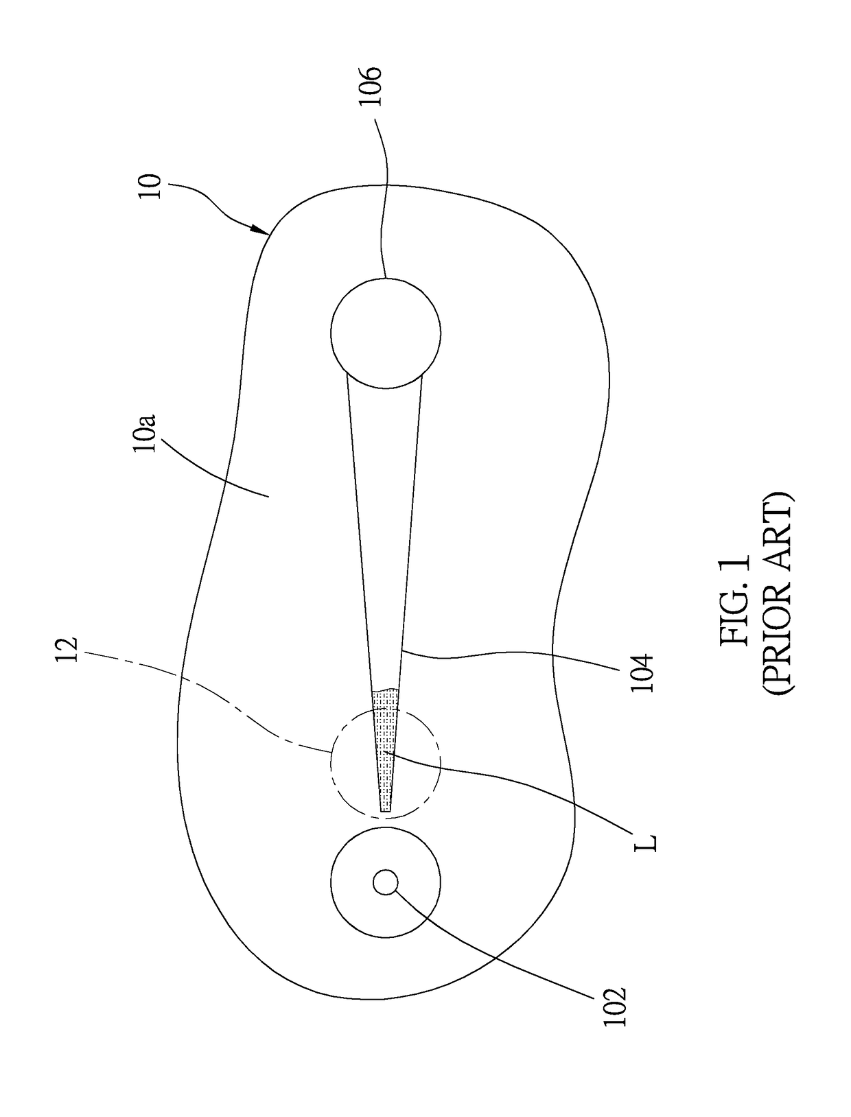
Once the lubricant accumulates too much, the gas channel would be blocked, which would cause the gas flow to drop dramatically or even to be cut off completely while rotating the plug member 10.

Method used


Image

  • Plug member of gas valve
  • Plug member of gas valve
  • Plug member of gas valve

Examples


Embodiment Construction

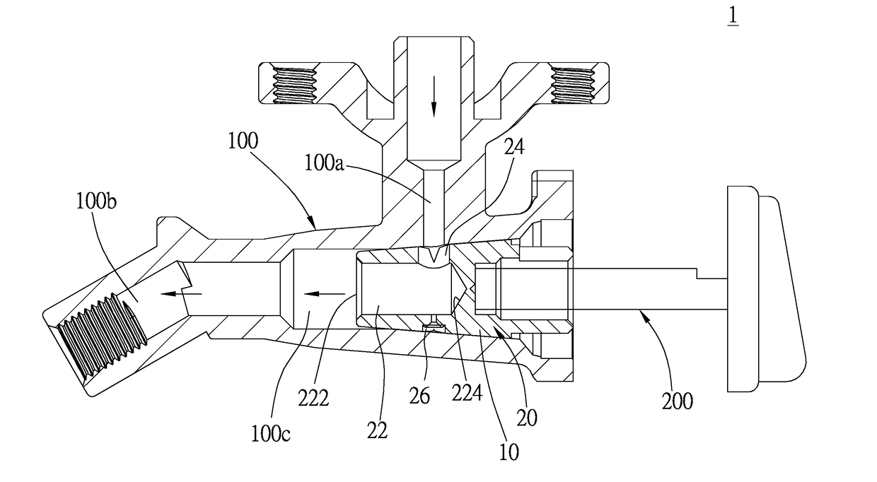
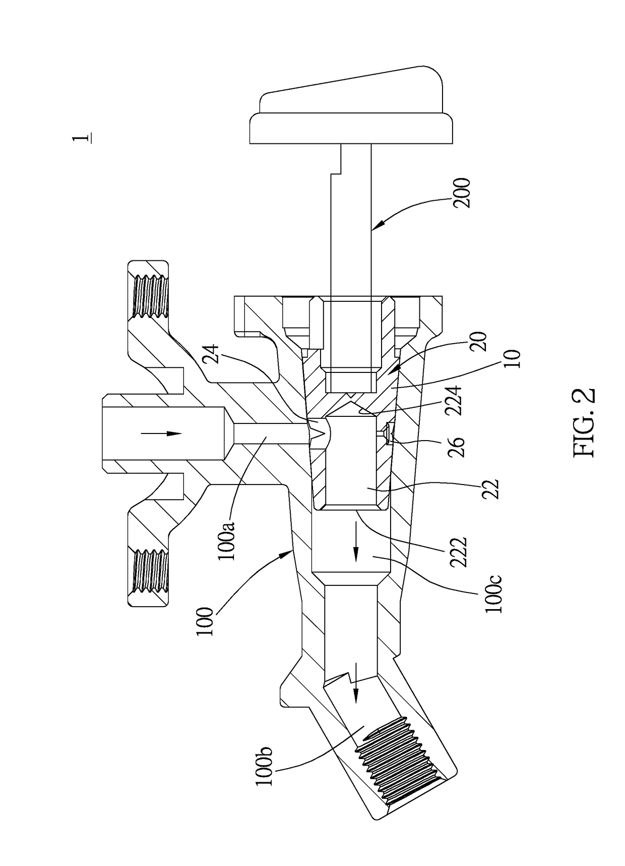
[0024]As shown in FIG. 2, a gas valve 1 with a plug member 20, which is the first embodiment of the present invention, has a valve 100 and a drive lever 200, wherein the drive lever 200 has a first airway 100a, a second airway 100b, and a chamber 100c communicating the first airway 100a and the second airway 100b. The plug member 20 is located in the chamber 100c of the valve 100, wherein lubricant is applied to an outer peripheral surface of the plug member 20 to make the plug member 20 rotate smoothly. The drive lever 200 is connected to the plug member 20 to rotate the plug member 20. In the first embodiment, gas flows in the gas valve 1 through the first airway 100a, and flows out through the second airway 100b. However, this is not a limitation of the present invention. Gas could flow in the gas valve 1 through the second airway 100b, and flow out through the first airway 100a in other embodiments.

[0025]As shown in FIGS. 3-6, the plug member 20 has an axial bore 22 located in a...


PUM


Abstract

A plug member of gas valve has an axial bore, a first bore, and a second bore, wherein the first bore and the second bore are located in a radial direction of the plug member, and communicate with the axial bore, respectively. A diameter of the first bore is larger than that of the second bore. A first guiding slot and at least one first oil groove are recessed into the outer peripheral surface of the plug member, wherein the first guiding slot has a first end communicating with the first bore, and a second end near the second bore without physically communicating with the second end. The at least one first oil groove is near the second end of the first guiding slot without physically communicating with the first guiding slot or the second bore. Whereby, the first oil groove provides space for receiving lubricant.

Description

[0001]The current application claims a foreign priority to application number 104135145 filed on Oct. 26, 2015 in Taiwan.BACKGROUND OF THE INVENTION[0002]1. Technical Field[0003]The present invention generally relates to a gas valve, and more particularly to a plug member of gas valve.[0004]2. Description of Related Art[0005]It's well known that a plug member installed in a gas valve is adapted to regulate the gas flow passing therethrough. Taiwan utility model patent M276159 discloses such a conventional plug member which is adapted to be installed in a main body of a gas valve, including a gas channel provided therein, wherein a first vent and a second vent communicating with the gas channel are provided on an outer wall of the plug member. A variable area slot is further provided on the outer wall of the plug member. The disclosed plug member is adapted to regulate gas flow passed through the gas valve in a nearly linear way, for the cross area of the variable area slot is specif...

Claims


Application Information

Patent Timeline
IPC IPC(8): F16K5/22F16K5/02
CPCF16K5/0207F16K5/222F23N2235/24F23N2235/16F23N1/007F23K2900/05002F16K5/0214
Inventor HUANG, CHUNG-CHINHUANG, CHIN-YINGHUANG, HSIN-MINGHUANG, HSING-HSIUNGYEH, YEN-JEN
Owner GRAND MATE
Learn More