Monitoring system and control method thereof

a monitoring system and control method technology, applied in the field of monitoring systems, can solve the problems of user's inability to adjust the size and position of the sub-windows, user's inflexible use, and may miss some important information, and achieve the effects of simple drag-and-drop operation, high security, and flexible us

Inactive Publication Date: 2017-04-27
DYNACOLOR
View PDF4 Cites 5 Cited by
  • Summary
  • Abstract
  • Description
  • Claims
  • Application Information

AI Technical Summary

Benefits of technology

[0013]The monitoring system according to the embodiments of the present invention have the following advantages:
[0014](1) In one embodiment of the present invention, after the coverage of any one of the sub-windows is modified, such as being enlarged, minified, reshaped, or moved, the monitoring system can automatically push or pull at least one of the other sub-windows, or minify the modified sub-window to prevent these sub-window from overlapping the enlarged, minified, reshaped, or moved sub-window. Therefore, the user will never miss any important information, so the monitoring system according to the present invention can achieve higher security.
[0015](2) In one embodiment of the present invention, the user can adjust the sub-windows of the monitoring system by an intuitive drag-and-drop operation instead of complicated operation interface. Thus, the monitoring system according to the present invention can provide a more user-friendly operation interface.
[0016](3) In one embodiment of the present invention, the user ca

Problems solved by technology

Thus, once one of the sub-windows is enlarged, the user cannot see all of the sub-windows; for the reason, the conventional monitoring system cannot always display all sub-windows.
In this way, the user may miss some important information when some sub-windows are covered by the enlarged sub-window.
In general, the conventional monitoring system only provides several fixed modes to display the sub-windows; therefore, in most cases, the user cannot adjust the size and the position of the sub-windows at will, which is not flexible in use.
Besides, generally speaking, the conventional monitoring system is very hard to operate because the user usually needs to click various icons on the scr

Method used


Image

  • Monitoring system and control method thereof
  • Monitoring system and control method thereof
  • Monitoring system and control method thereof

Examples


first embodiment

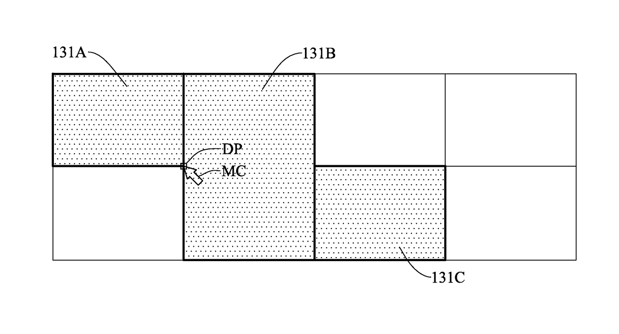
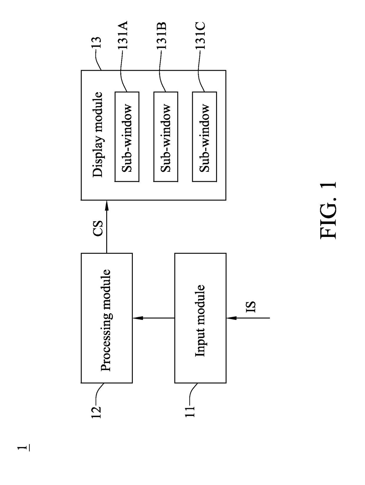
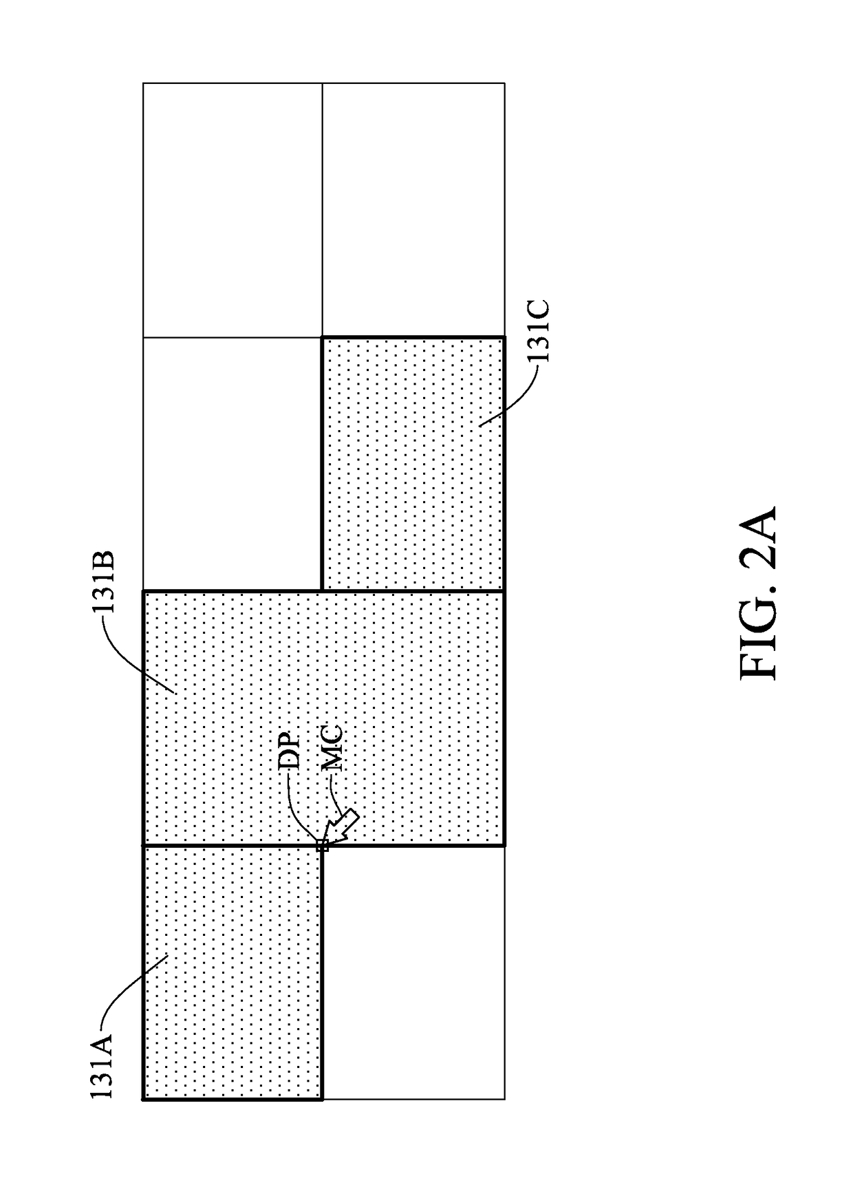
[0050]Please refer to FIG. 2A, FIG. 2B, FIG. 2C, and FIG. 2D, which are the first schematic view, second schematic view, third schematic view, and fourth schematic view of the monitoring system in accordance with the present invention. The embodiment illustrates one of the preferred operation modes of the monitoring system according to the present invention. The user can use a pointer device, such as a mouse, to intuitively modify the coverage of any one of the sub-windows 131A, 131B, 131C, 131D, and 131E of the display module 13 by a simple drag-and-drop operation; for example, the user may enlarge, minify, reshape, or move any one of the sub-windows 131A, 131B, 131C, and 131D to change its coverage by the pointer device.

[0051]As shown in FIG. 2A, the user can move the mouse cursor MC to the drag point DP of the sub-window 131A to drag the drag point DP to another position of the display module 13 so as to enlarge the sub-window 131A; the drag point DP may be any one of the corners...

second embodiment

[0054]Please refer to FIG. 3A, FIG. 3B, FIG. 3C, and FIG. 3D, which are the first schematic view and, second schematic view, third schematic view, and fourth schematic view of the monitoring system in accordance with the present invention. The embodiment illustrates one of the preferred operation modes of the monitoring system according to the present invention.

[0055]As shown in FIG. 3A, the user can move the mouse cursor MC to the drag point DP of the sub-window 131A to drag the drag point DP to another position of the display module 13 so as to minify the sub-window 131A.

[0056]As shown in FIG. 3B, after the sub-window 131A is minified, the processing module may execute a first recursive function to detect whether the sub-window 131A overlaps the other sub-windows 131 B and 131C. If detecting the sub-window 131A fails to overlap any one of the other sub-windows 131B and 131C, the processing module may execute a second recursive function to detect whether the original distance betwe...

third embodiment

[0060]Please refer to FIG. 4A, FIG. 4B, and FIG. 4C, which are the first schematic view, second schematic view, and third schematic view of the monitoring system in accordance with the present invention. The embodiment illustrates one of the preferred operation modes of the monitoring system according to the present invention.

[0061]As shown in FIG. 4A, the user can move the mouse cursor MC to the drag point DP of the sub-window 131A to drag the drag point DP to another position of the display module 13 so as to move the sub-window 131A to the position between the sub-window B and sub-window C, and then the coverage of the sub-window 131A may be adjusted according to the residual space of the display module 13; the drag point DP may be any point of the sub-window A.

[0062]As shown in FIG. 4B, after the sub-window 131A is moved to overlap the sub-window 131B, the processing module may automatically calculate the proper length and width of the sub-window 131A according to the residual s...


PUM


Abstract

A monitoring system may include a display module, an input module, and a processing module. The display module may be operable to display a plurality of sub-windows. The input module may be operable to receive an input signal inputted by a user and generate a control signal according to the input signal. The processing module may be operable to receive the control signal to control any one of the sub-windows of the display module according to the control signal. When the coverage of any one of the sub-windows is modified by the user, the processing module will execute a first recursive function to detect whether the modified sub-window overlaps any one of the other sub-windows; if the modified sub-window overlaps any one of the other sub-windows, the processing module pushes the sub-window overlapping the modified sub-window to a residual space of the display module.

Description

BACKGROUND OF THE INVENTION[0001]1. Field of the Invention[0002]The present invention generally relates to a monitoring system, in particular to a monitoring system with multiple functions. The present invention further relates to the control method of the monitoring system.[0003]2. Description of the Related Art[0004]Nowadays, as people pay more attention to their security and safety, monitoring system has become a very important device for everyone. However, the conventional monitoring system has a lot of shortcomings to be overcome.[0005]For example, if a user wants to see more details of one of the sub-windows of the conventional monitoring system, the user should enlarge this sub-window. However, after the sub-window is enlarged, the other sub-windows may be covered by the enlarged sub-window. Thus, once one of the sub-windows is enlarged, the user cannot see all of the sub-windows; for the reason, the conventional monitoring system cannot always display all sub-windows. In thi...

Claims


Application Information

Patent Timeline
IPC IPC(8): G06F3/0484
CPCG06F2203/04803G06F3/04845G06F3/0484G06F2203/04806G06F9/451
Inventor HUANG, CHENG-HANLEE, TSUNG-TSE
Owner DYNACOLOR
Why Eureka
Try Eureka