Flow battery

a flow battery and flow current technology, applied in the field of flow batteries, can solve the problem of a decrease in power output of flow batteries

Active Publication Date: 2017-04-27
TOYOTA JIDOSHA KK
View PDF0 Cites 2 Cited by
  • Summary
  • Abstract
  • Description
  • Claims
  • Application Information

AI Technical Summary

Benefits of technology

[0013]According to the disclosed embodiments, the flow battery that is able to prevent the discharge inhibition by trapping the lithium-containing deposits produced upon the chemical oxidation of the reduced mediator before they reach the cathode, can be provided.

Problems solved by technology

Therefore, the flow battery has a problem of a decrease in power output.

Method used


Image

  • Flow battery
  • Flow battery
  • Flow battery

Examples


first example

[0063]When the size of the lithium-containing deposits is in micrometers to millimeters, as shown in FIG. 3, a filter may be disposed in the trap. As the filter, metal mesh, carbon paper, carbon cloth, filter paper or the like may be used.

[0064]If the pore diameter or porosity of the filter is too large, the lithium-containing deposits cannot be efficiently trapped. If the pore diameter or porosity is too small, the back pressure of the electrolyte increases. Therefore, the pore diameter and porosity of the filter are determined depending on the size of the lithium-containing deposits and the circulation rate of the electrolyte.

[0065]The pore diameter of the filter may be in a range of 500 nm to 2 mm or may be in a range of 1 μm to 5 μm.

[0066]The porosity of the filter may be in a range of 50 to 90% or may be in a range of 60 to 80%.

second example

[0067]When the lithium-containing deposits are submicron or below in size, as shown in FIG. 4, an electrolyte withdrawal valve may be disposed in the trap. In addition to the electrolyte withdrawal valve, a separator for separating the lithium-containing deposits from the withdrawn electrolyte and trapping the separated lithium-containing deposits, may be disposed in the trap. As described above, due to the pore diameter or porosity problem, the filter being able to trap the lithium-containing deposits being submicron in size, increases the back pressure of the electrolyte. Therefore, it is not suitable to dispose the filter in the trap.

[0068]Therefore, it is suitable that the electrolyte withdrawal valve is disposed in the trap to withdraw the electrolyte to the outside; the electrolyte and the lithium-containing deposits are separated from each other; and then only the electrolyte is returned to the flow battery.

[0069]The electrolyte and the lithium-containing deposits may be sepa...

third example

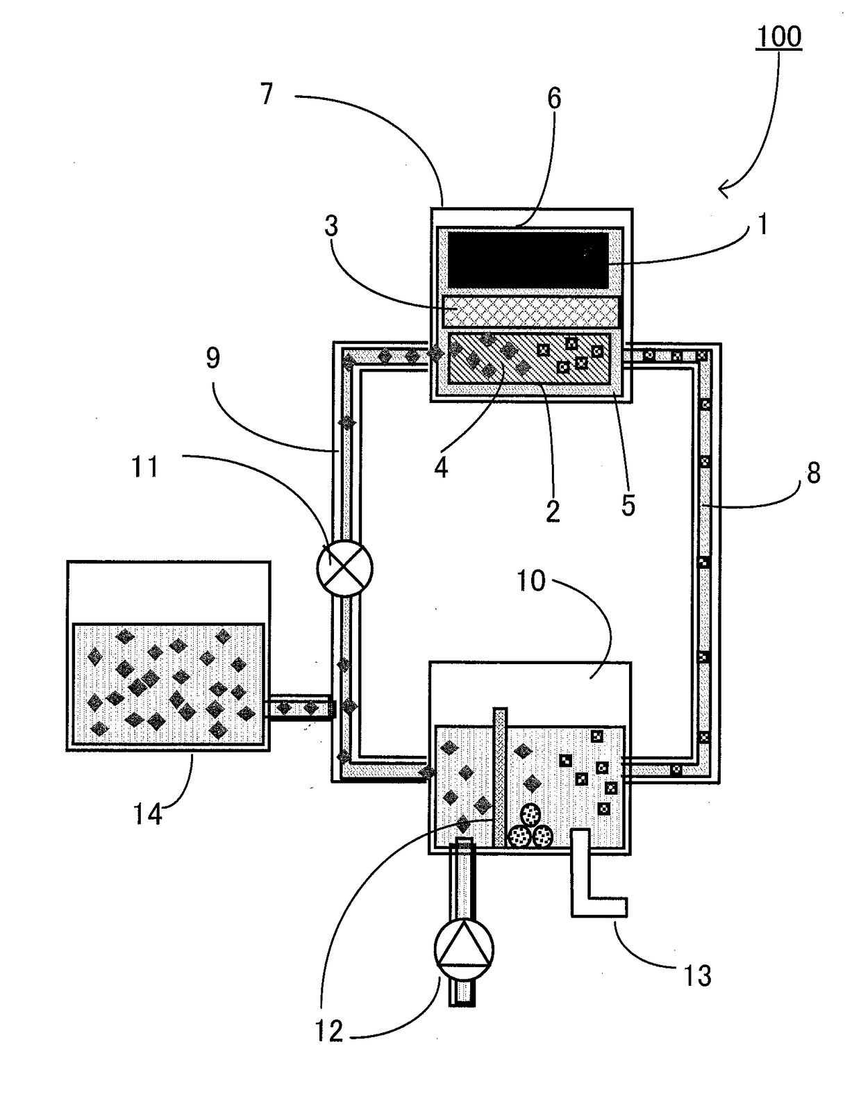
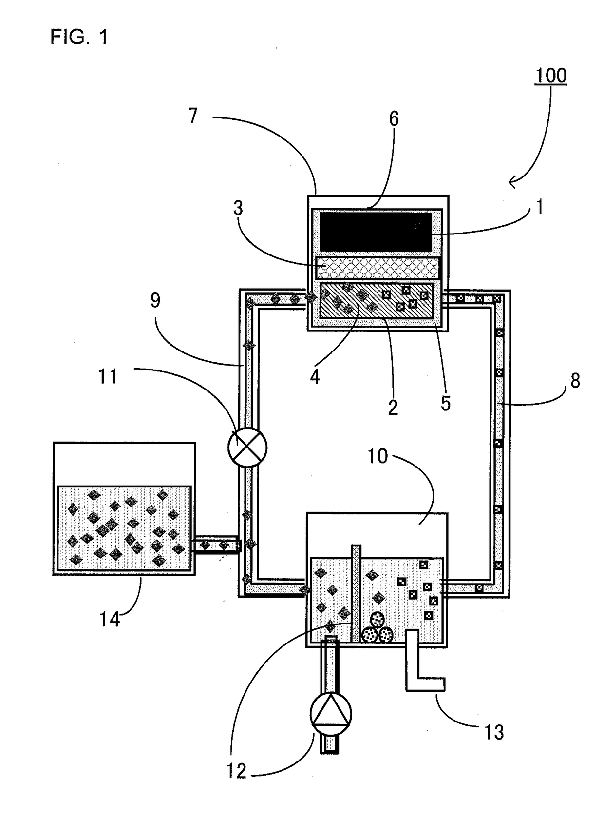
[0071]When the size of the lithium-containing deposits cannot be supposed or varies depending on discharge conditions, as shown in FIG. 1, the filter and the electrolyte withdrawal valve may be disposed in the trap.

[0072]As a result, the number of the components constituting the trap is increased, thereby increasing the size of the system. However, it is particularly effective when the flow battery is used under the condition that it is difficult to suppose the type or size of the lithium-containing deposits produced upon the chemical oxidation of the mediator.


PUM

PropertyMeasurementUnit
poweraaaaaaaaaa
energy densityaaaaaaaaaa
chemically stableaaaaaaaaaa

Abstract

A flow battery that prevents discharge inhibition caused by lithium-containing deposits produced with chemical oxidation of mediator. Flow battery includes: anode including anode current collector having lithium element on a surface thereof; cathode including cathode current collector; separator disposed between anode and cathode; electrolyte including mediator having function as a redox couple; discharger including reductor and anode chamber, reductor being defined by separator, housing cathode and electrolyte and being configured to reduce the mediator, anode chamber housing the anode defined by separator; first flow channel and second flow channel, flow channels being connected to reductor; oxidizer connected to first and second flow channels; configured to chemically oxidize the mediator; circulator configured to circulate electrolyte to reductor, first flow channel, oxidizer and second flow channel in this order, wherein a trap configured to trap lithium-containing deposits produced with oxidation of mediator, disposed in part of the second flow channel or oxidizer.

Description

TECHNICAL FIELD[0001]The disclosure relates to a flow battery.BACKGROUND[0002]A flow battery is a battery in which a redox couple (mediator) is reacted, and it is not a battery in which a reductant and an oxidant are directly reacted in at least one electrode.[0003]A lithium semi-redox flow battery is disclosed in Patent Literature 1. The flow battery comprises a combination of the cathode of a redox flow battery and an anode that uses lithium as an active material, and the flow battery is able to regain a cathode active material by both of electrical charging and chemical oxidation caused by addition of an oxidant.[0004]Patent Literature 1: Japanese Patent Application Laid-Open No. 2013-26142SUMMARY[0005]However, it was found that in the flow battery using a lithium element as the anode active material, depending on the structure or the state of use of the battery, lithium-containing deposits may be produced upon the chemical oxidation of a mediator reduced by discharge. Once the l...

Claims


Application Information

Patent Timeline
Patent Type & Authority Applications(United States)
IPC IPC(8): H01M8/18H01M12/08H01M8/04186H01M8/20
CPCH01M8/188H01M8/20H01M2300/0028H01M8/04186H01M12/08H01M8/18Y02E60/50
Inventor NITTA, IWAO
Owner TOYOTA JIDOSHA KK
Why Eureka
Try Eureka