Molded Surface Fastener and Molded Surface Fastener Manufacturing Method

a manufacturing method and technology of molded surfaces, applied in the direction of eye fasteners, hook fasteners, apparel, etc., can solve the problem that the cushion body cannot be applied, and achieve the effect of easy correspondance, increased peeling resistance of the space region of the die wheel, and enhanced connection portion strength

Active Publication Date: 2017-05-04
YKK CORP
View PDF1 Cites 9 Cited by
  • Summary
  • Abstract
  • Description
  • Claims
  • Application Information

AI Technical Summary

Benefits of technology

[0051]The molded surface fastener according to the invention includes engaging regions having a plurality of engaging elements and space regions having a flat surface on which the engaging elements are excluded on the substrate portion alternately in the length direction. The engaging region has a pair of left and right resin intrusion barrier portions standing along the length direction and main lateral wall portions standing along the width direction so as to compart from the space region. The space region has a pair of left and right vertical wall portions standing along the length direction at left and right side edge portions of the substrate portion and a convex rib portion projecting integrally from the substrate portion along the length direction at a center portion in the width direction of the substrate portion, and the convex rib portion is integrally connected to the main lateral wall portion adjacent in the length direction of the space region.
[0052]For such a molded surface fastener of the present invention, a plurality of surface fastener members can be provided with a shape connected with each other by flexible connecting portions including the convex rib portion by performing an easy cutting processing to cut off the space region so that at least the convex rib portion is remained. Therefore, it can easily correspond to a curve-shaped usage bending in the width direction without using other members such as polystyrene foam or a nonwoven fabric as in the above mentioned Patent Document 3 or a monofilament as in Patent Document 4.
[0053]Further, in this case, a strength of the connecting portion can be enhanced because the convex rib portion forming the connecting portion is formed to project integrally from the substrate portion and integrally connected to the main lateral wall portion of the engaging region adjacent frontward or backward. In addition, a relative position relation between the convex rib portion and the substrate portion or the main lateral wall portion can be stably maintained, thereby a twist between the surface fastener members connected by the connecting portion hardly occurs.
[0054]Also in the present invention, when the molded surface fastener is molded using a die wheel in which a cavity space for engaging elements and the like is recessed on the periphery, a pair of left and right vertical wall portions and the convex rib portion are disposed on the substrate portion in the space region. The pair of left and right vertical wall portions disposed in the space region become rather encumbrance at the time of cutting processing to correspond to the curve-shaped usage, as described later. However, since the pair of left and right vertical wall portions and the convex rib portion are disposed in the space region, a peeling resistance to peel off the part of the space region from the die wheel can be increased, and non-evenness of the peeling force of the molded surface fastener in the length direction of the molded surface fastener can be suppressed. Thereby, the engaging elements arranged close to the space region hardly receive a large force when the molded surface fastener is peeled off from the die wheel, and the molded surface fastener having a predetermined shape can be stably formed.
[0055]Further, in the present invention, the engaging region having a plurality of the engaging elements and the space region without the engaging elements are disposed alternately in the length direction. Therefore, when the above mentioned cutting processing is performed to correspond to a curve-shaped usage, for example, the positioning member detecting a position of the molded surface fastener can be stably inserted into the space region of the molded surface fastener, and the position of the molded surface fastener can be precisely and promptly detected. Therefore, the cutting processing can be performed accurately and efficiently. Also, since the engaging elements are not disposed on the space region, insertion of the positioning member into the space region does not lead to deformation or breakage of the engaging elements in the engaging region.
[0056]In the molded surface fastener of the present invention, the substrate portion, the resin intrusion barrier portion, the main lateral wall portion, the vertical wall portion and the convex rib portion are formed using the same thermoplastic resin. Thereby respective portions of the molded surface fastener can be formed integrally and firmly, the molding process can be prevented from being complexed, and the molded surface fastener can be manufactured efficiently.

Problems solved by technology

Accordingly, the molded surface fastener of Patent Document 1 or Patent Document 2 has a defect that it cannot be applied to a cushion body in which the molded surface fastener needs to be integrated in a bent state in the width direction.

Method used


Image

  • Molded Surface Fastener and Molded Surface Fastener Manufacturing Method
  • Molded Surface Fastener and Molded Surface Fastener Manufacturing Method
  • Molded Surface Fastener and Molded Surface Fastener Manufacturing Method

Examples


embodiment 1

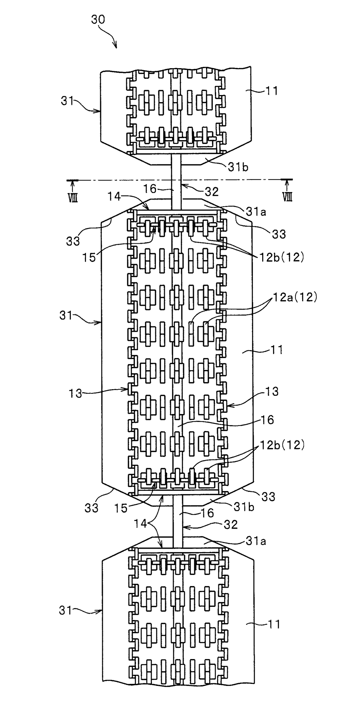
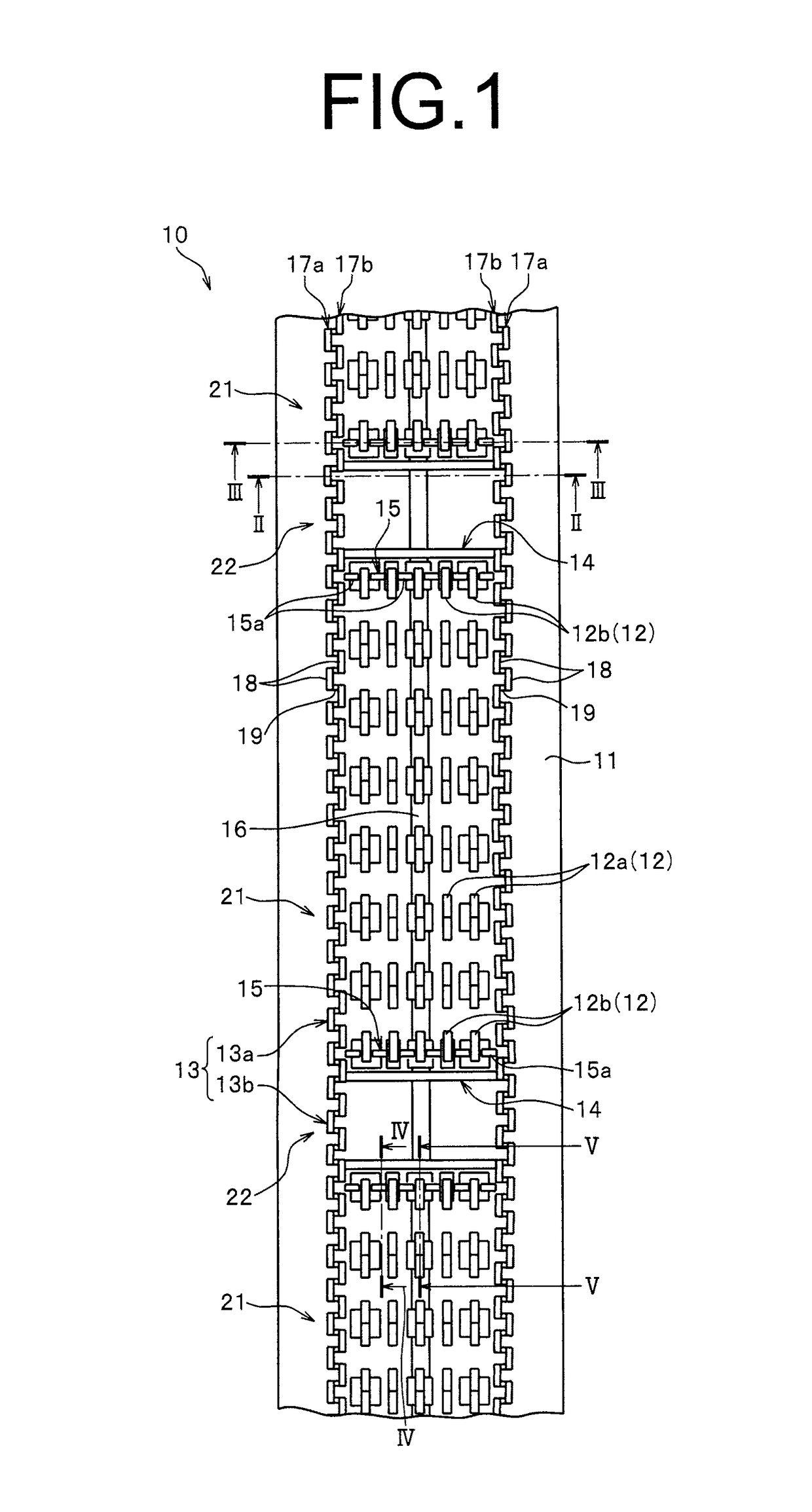
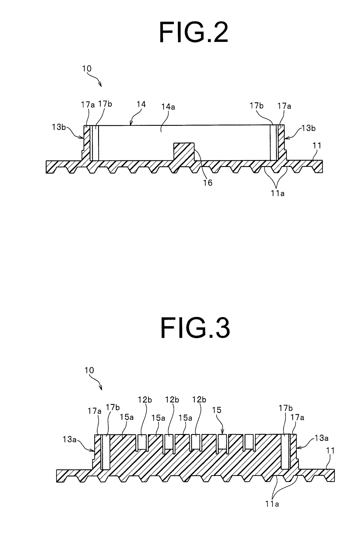
[0093]FIG. 1 is a plan view illustrating a molded surface fastener according to Embodiment 1, and FIG. 2 to FIG. 5 are cross-sectional views along the lines II-II to V-V, respectively, in FIG. 1.

[0094]In the following descriptions, a longitudinal direction of the substrate portion in the molded surface fastener is defined as a front and rear direction, and a width direction of the substrate portion is defined as a left and right direction. A top and bottom direction of the substrate portion is defined as a vertical direction, and particularly, a direction in which engaging elements are disposed with respect to the substrate portion is referred to as “upper”, and an opposite direction is referred to as “lower”.

[0095]A molded surface fastener 10 according to Embodiment 1 is formed to be long in the length direction by molding a thermoplastic resin material using a die wheel 41, as described later. A material of the molded surface fastener 10 is not limited, and a single thermoplastic ...

embodiment 2

[0211]FIG. 15 is a plan view illustrating a molded surface fastener according to Embodiment 2, and FIG. 16 is a cross-sectional view along the line XVI-XVI in FIG. 15.

[0212]Regarding a molded surface fastener 70 according to Embodiment 2 and a molded surface fastener 80 according to Embodiment 3, as described later, structural features different from the molded surface fastener 10 of Embodiment 1 will be mainly described, and parts and members having substantially same as those of the molded surface fastener 10 of Embodiment 1 will not be described but represented by the same reference numerals.

[0213]In the molded surface fastener 70 according to Embodiment 2, in addition to the structural features of the straight-shaped molded surface fastener 10 according to the above-mentioned Embodiment 1, a plurality of auxiliary divided wall bodies 71a are disposed along the width direction at a position of a lateral row of the first engaging elements 12a disposed in line in the engaging regio...

embodiment 3

[0219]FIG. 17 is a side view of a molded surface fastener according to Embodiment 3.

[0220]In a straight-shaped molded surface fastener 80 of Embodiment 3, a height dimension of the vertical wall portion 83b disposed in the space region 22 from the substrate portion 11 is configured to be lower than that of the straight-shaped molded surface fastener 10 according to Embodiment 1, and other than that, it has the same structure as the straight-shaped molded surface fastener 10 according to the above-mentioned Embodiment 1.

[0221]That is, the height dimension of the vertical wall portion 83b disposed in the space region 22 of Embodiment 3 from the substrate portion 11 is lower than that of the resin intrusion barrier portion 13a disposed in the engaging region 21. As the vertical wall portion 83b having a lower height and the convex rib portion 16 are disposed in the space region 22, when the straight-shaped molded surface fastener 80 according to Embodiment 3 is molded using the molding...


PUM

PropertyMeasurementUnit
lengthaaaaaaaaaa
widthaaaaaaaaaa
thermoplasticaaaaaaaaaa

Abstract

A molded surface fastener has engagement regions in which engaging elements are disposed in an erect manner and space regions with no engaging elements, the engagement regions and the space regions alternating in the longitudinal direction. Each space region has a pair of left and right vertical wall portions that are disposed on a substrate portion in an erect manner and a convex rib portion that protrudes from the center of the substrate portion in the width direction, and the convex rib portion is integrally connected to a main lateral wall portion disposed in the width direction of the engagement region. By implementing a simple cutting process, this molded surface fastener can be easily adapted to usages in which the fastener has to be in a curved shape bending in the width direction.

Description

TECHNICAL FIELD[0001]The present invention relates to a molded surface fastener that is integrated on a surface of a cushion body when the cushion body is foamed and molded, and a manufacturing method of the molded surface fastener. Particularly, the present invention relates to a molded surface fastener which can prevent a foam resin material from intruding into an engaging region when the cushion body is foamed and molded, and a manufacturing method of the molded surface fastener.BACKGROUND ART[0002]Passenger seats of automobiles or trains, various kinds of sofas, office chairs, and the like are often formed by attaching a skin material such as fiber fabric or natural or synthetic leather to the surface of a cushion body (foaming body) molded in a predetermined shape by using a foam resin material. The cushion body used in these various seats often has a bent surface composed of convex-concave shapes satisfying human engineering factors in order to maintain a seating posture which...

Claims


Application Information

Patent Timeline
Patent Type & Authority Applications(United States)
IPC IPC(8): A44B18/00A44B13/00
CPCA44B18/0076A44B13/0023A44B18/0049A44B13/0052A44B13/0047A44B18/0069A44B18/00A44B18/0007
Inventor OKUDA, KENJITERADA, MINETOIMAI, SHINICHIMINATO, TSUYOSHI
Owner YKK CORP
Why Eureka
Try Eureka