Sensor mounting in an implantable blood pump

a technology of implantable blood pump and sensor, which is applied in the direction of instruments, prosthesis, printed circuit non-printed electric components association, etc., can solve the problems of placing these sensors

Active Publication Date: 2017-05-04
TC1 LLC
View PDF8 Cites 11 Cited by
  • Summary
  • Abstract
  • Description
  • Claims
  • Application Information

AI Technical Summary

Benefits of technology

[0006]When monitoring or controlling an electromagnetically levitated rotating object, it is useful to have sensors placed about the circumference of the rotating object to monitor its angular position, angular velocity, and any offsets from its ideal rotating axis. Placing these sensors can be challenging from the perspective of locating each sensor axially symmetric to the other sensors and facilitating an assembly process that does not impose mechanical stresses on the sensor package electrical interconnects.

Problems solved by technology

Placing these sensors can be challenging from the perspective of locating each sensor axially symmetric to the other sensors and facilitating an assembly process that does not impose mechanical stresses on the sensor package electrical interconnects.

Method used


Image

  • Sensor mounting in an implantable blood pump
  • Sensor mounting in an implantable blood pump
  • Sensor mounting in an implantable blood pump

Examples


Embodiment Construction

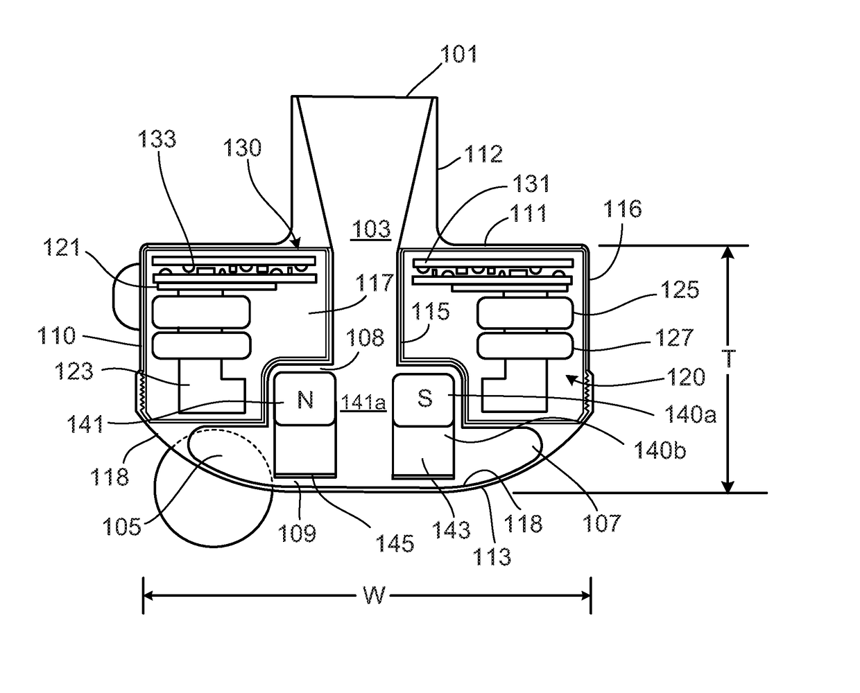
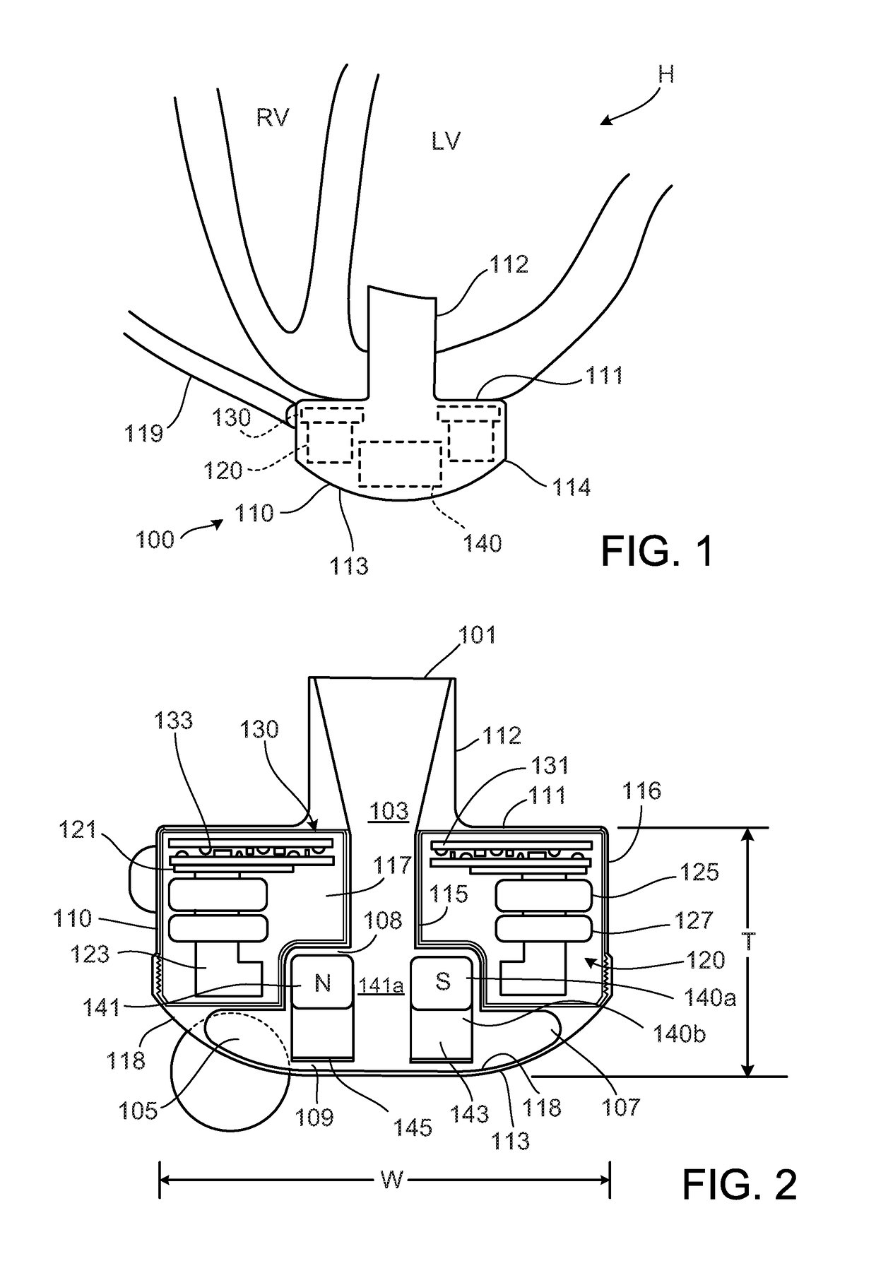
[0084]This description relates to mounting a sensor, such as a Hall sensor, in an implantable blood pump.

[0085]The subject matter described in this disclosure can be implemented in particular aspects or embodiments so as to realize one or more of the following advantages.

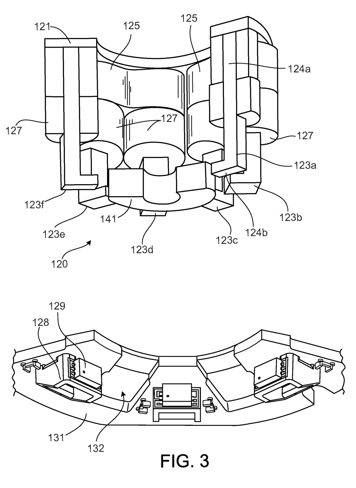
[0086]First, a molded interconnect device may allow a Hall sensor to be positioned at an adequate position within the blood pump, while the device may be inserted into the pump with insertion machines employed for the assembly of the pump. For example, the implementations or aspects described herein allow a Hall sensor to be positioned and mounted on a printed circuit board of a stator of the pump thereby allowing the Hall sensor to transduce a position of a rotor during operation of the pump.

[0087]Second, mechanical stress on integrated electronic conductive traces of the molded interconnect device may be reduced and may thereby enhance the robustness of a connection between the device and a printed circuit board. ...


PUM

PropertyMeasurementUnit
widthaaaaaaaaaa
thicknessaaaaaaaaaa
thicknessaaaaaaaaaa

Abstract

Techniques for mounting a sensor are disclosed. In some implementations, a molded interconnect device carries a sensor for transducing a position of a rotor of the implantable blood pump. The molded interconnect device includes one or more integrated electronic circuit traces configured to electrically connect the Hall sensor with a printed circuit board of the implantable blood pump, and the molded interconnect device is configured to be mounted to the printed circuit board.

Description

CROSS-REFERENCES TO RELATED APPLICATIONS[0001]This application is a divisional of U.S. patent application Ser. No. 14 / 015,630, filed Aug. 30, 2013, which application claims the benefit of U.S. Provisional Application No. 61 / 695,624, filed Aug. 31, 2012, the full benefit of which are incorporated herein in their entirety for all purposes.[0002]The description relates to United States Published Application No. 2012 / 0046514, filed Aug. 18, 2011, and titled “Implantable Blood Pump,” the entire contents of which are incorporated herein by reference.FIELD[0003]This description relates to mounting a sensor in a device, for example, mounting a Hall sensor in an implantable blood pump.BACKGROUND[0004]Ventricular assist devices, known as VADs, are implantable blood pumps used for both short-term and long-term applications where a patient's heart is incapable of providing adequate circulation. For example, a patient suffering from heart failure may use a VAD while awaiting a heart transplant. ...

Claims


Application Information

Patent Timeline
Patent Type & Authority Applications(United States)
IPC IPC(8): A61M1/10G01D5/14H05K1/18H05K3/30A61M1/12H05K1/11A61M60/178A61M60/216A61M60/422A61M60/515A61M60/538
CPCA61M1/1086A61M1/1036A61M1/122H05K1/119H05K1/189H05K2201/10151G01D5/142A61M2205/3317A61M2207/00A61M2205/3365H05K3/303H05K3/4691H05K2201/052F04D15/0077A61M2205/3334G01B7/003Y10T29/49009Y10T29/49128F04D13/064G01B7/30A61M60/824A61M60/422A61M60/148A61M60/216A61M60/538A61M60/178A61M60/515H05K1/028H05K3/30A61M60/419G01R33/072H05K3/32
Inventor MCCHRYSTAL, MARKSTARK, III, JOSEPH C.
Owner TC1 LLC
Why Eureka
Try Eureka