Sealless rotary blood pump

a rotary, blood pump technology, applied in the field of blood pumps, can solve the problems of frequent hospitalization, severe physical disability, and variety of anatomical and engineering problems, and achieve the effects of shortening the residence time, efficient pump operation, and minimizing the likelihood of blood thrombosis

Inactive Publication Date: 2009-08-18
THORATEC CORPORTION
View PDF88 Cites 141 Cited by
  • Summary
  • Abstract
  • Description
  • Claims
  • Application Information

AI Technical Summary

Benefits of technology

[0015]One thrust bearing is included at the upstream end of the support shaft, and the other thrust bearing is located on the bottom, or downstream side of the impeller. A spider within the inlet tube includes a touchdown, or thrust surface, against which the end of the shaft periodically touches. Another touchdown is provided on an inner surface of the casing base, adjacent a downstream terminus of the impeller. A predetermined amount of spacing is included between the two touchdowns, so as to allow the shaft / impeller assembly axially to shuttle back and forth, in response to the user's cardiac cycle. This shuttling motion will produce a pumping action, frequently exchanging blood in the touchdown area with fresh blood from the circulation. This pumping action minimizes the likelihood of blood thrombosis in the thrust region, by maintaining the blood at an acceptable temperature and by shortening its residence time in the thrust bearing gap.
[0016]The impeller is of unique configuration and characteristics, owing to the special requirements of the present application. Contrary to conventional centrifugal pump design, the present invention uses relatively few impeller blades, generally resembling pie-shaped sectors. Moreover, the blades are made quite thick in an axial direction, having deep and narrow, arcuate channels between adjacent blades for the passage of blood through the impeller. The substantial height of the blades provides a relatively large blade working surface, ensuring efficient pump operation. These structural features decrease hemolysis of the blood, while containing useful efficiency in a pump using so few impeller blades.
[0017]Sealed, hollow chambers are provided within the thick impeller blades to reduce the density of the impeller. These chambers reduce gravity induced loads on the thrust bearings, which in turn reduces the likelihood of thrombosis of the blood used to lubricate the bearings.
[0018]The thick impeller blades are also used advantageously to house magnets used in the pump drive system. Torque drive is imparted to the impeller by magnetic interaction between arcuate, permanent magnetic segments imbedded within each impeller blade sector, and a circular electromagnetic stator, affixed to the casing. Back-EMF sensing is used to commutate the brushless motor stator, providing attractive and repulsive forces upon the magnetic segments. A control unit and a portable power supply, worn on the user, power the pump drive system. The control unit allows the speed and drive cycle of the motor either to be programmed or interactively determined by the user's physical activity or condition.

Problems solved by technology

However, owning to a shortage of donor hearts, most of these patients face a foreshortened life span characterized by frequent hospitalizations, severe physical disability, and death from congestive failure or cardiogenic shock.
This design approach has resulted in a variety of anatomic and engineering problems.
Cyclic delivery systems tend to be physically large, making implantation difficult or impossible for some patients.
All of these characteristics make cyclic blood pumping device both complex and expensive.
However, the prior art has not developed a durable rotary blood pump, owing to unique problems with the rotary pump's driveshaft seal.
In a blood environment, such driveshaft seals have a short life, and contribute to a premature failure of the pump.
Prior art driveshaft seals may also cause embolisms, resulting in a stroke or even death for the patient.

Method used


Image

  • Sealless rotary blood pump
  • Sealless rotary blood pump
  • Sealless rotary blood pump

Examples


Embodiment Construction

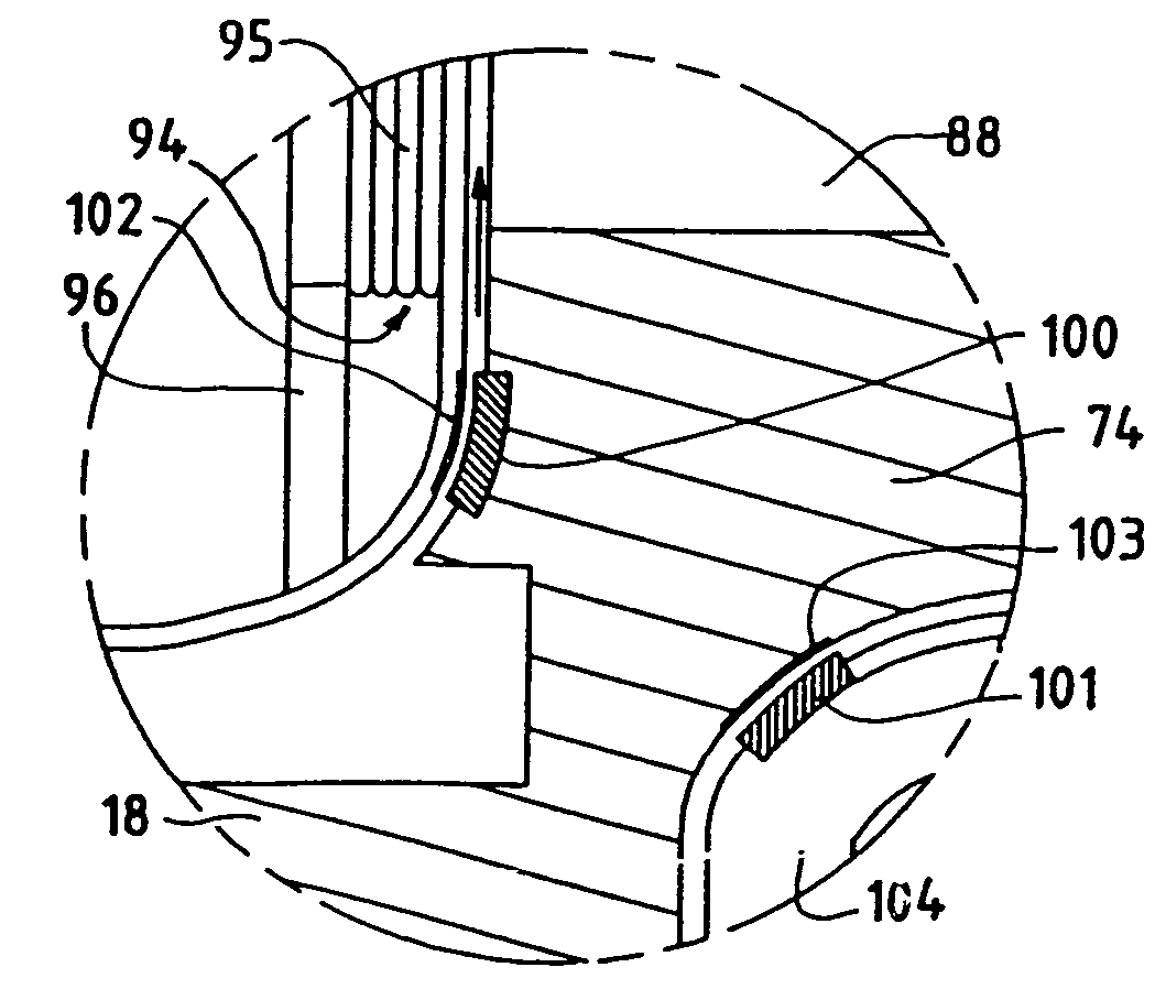
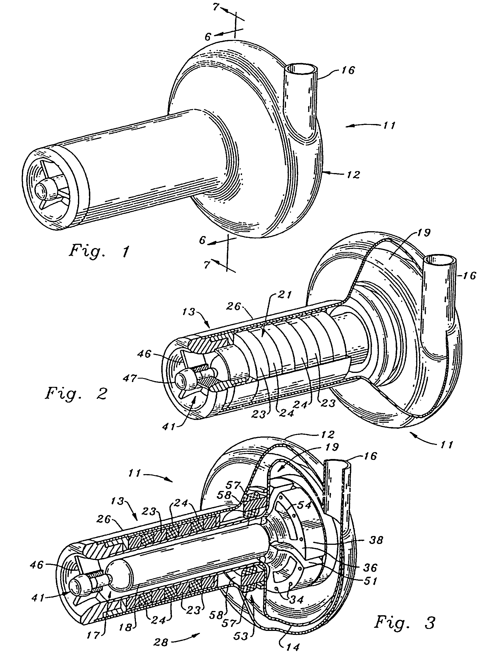
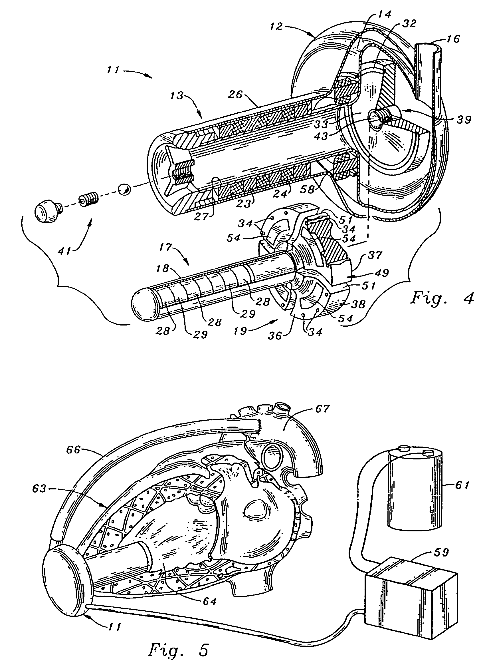
[0050]Turning now to FIGS. 1-8 of the drawings, a sealless rotary blood pump 11 includes a housing 12, having an elongated inlet tube 13 and an impeller casing volute 14. A discharge tube 16 extends through the housing to communicate with the interior periphery of casing 14. Tube 16 has a tangential orientation with respect to a radius of the casing, for effectively channeling the blood output from the pump.

[0051]A pump rotor 17 is located within housing 12, within casing 14, and includes an elongated, right-circular cylindrical support shaft or spindle 18, attached to a disc-shaped impeller 19. Rotor 17 is mounted for rotation about a longitudinal axis which extends both through shaft 18 and impeller 19. It should be noted that the preferred embodiment disclosed herein includes an impeller and a casing of centrifugal design. However, many of the structural features and aspects of operation of the present invention may also be adapted advantageously to rotary blood pumps of axial fl...


PUM


Abstract

A rotary blood pump is provided which includes a pump housing and a rotor mounted for rotation with the housing. The rotor has an impeller. A rotor motor is provided including a plurality of permanent magnets carried by the impeller. A first motor stator is positioned on one side of the impeller and a second motor stator is positioned on an opposite side of the impeller. The motor stators each include a plurality of electrically conductive coils and pole pieces located within the housing. A plurality of wedge-shaped hydrodynamic thrust bearings are located outside of the axis of the rotor. During rotation of the impeller, the hydrodynamic bearings are separated from the housing by a fluid film and are not in direct mechanical contact with the housing.

Description

[0001]This application is a continuation of application Ser. No. 10 / 034,873, filed Dec. 26, 2001, now U.S. Pat. No. 6,688,861, which is a continuation of application Ser. No. 09 / 689,251, filed Oct. 13, 2000, now U.S. Pat. No. 6,368,083, which is a continuation of application Ser. No. 09 / 420,997, filed Oct. 20, 1999, now U.S. Pat. No. 6,234,998, which is a continuation of application Ser. No. 09 / 108,434, filed Jul. 1, 1998, now U.S. Pat. No. 6,080,133, which is a division of application Ser. No. 08 / 910,375, filed Aug. 13, 1997, now U.S. Pat. No. 5,840,070, which is a continuation-in-part of application Ser. No. 08 / 603,536, filed Feb. 20, 1996, now U.S. Pat. No. 5,695,471.FIELD OF THE INVENTION[0002]The invention relates generally to the field of blood pumps. More specifically, the invention pertains to continuous flow pumps of rotary design, suitable for permanent implantation in humans for use as chronic ventricular assist devices.BACKGROUND OF THE INVENTION[0003]Thousands of heart ...

Claims


Application Information

Patent Timeline
Patent Type & Authority Patents(United States)
IPC IPC(8): F04B17/00A61M1/10F04D29/046F04D13/06F04D29/048F04D29/08F16C39/06H02K5/128H02K7/09H02K7/14H02K41/03
CPCA61M1/101F16C39/063H02K5/1285H02K7/09H02K7/14A61M1/125A61M1/1015A61M1/1031A61M1/122H02K41/03Y10S415/90F16C17/08F16C2316/18A61M60/82A61M60/824A61M60/422A61M60/148A61M60/232A61M60/178A61M60/538A61M60/515A61M1/00
Inventor WAMPLER, RICHARD K.
Owner THORATEC CORPORTION
Why Eureka
Try Eureka