

End seal structure of a fuel rail for a gasoline direct injection engine
- Summary
- Abstract
- Description
- Claims
- Application Information
AI Technical Summary
Benefits of technology
Problems solved by technology
Method used
Image

Examples
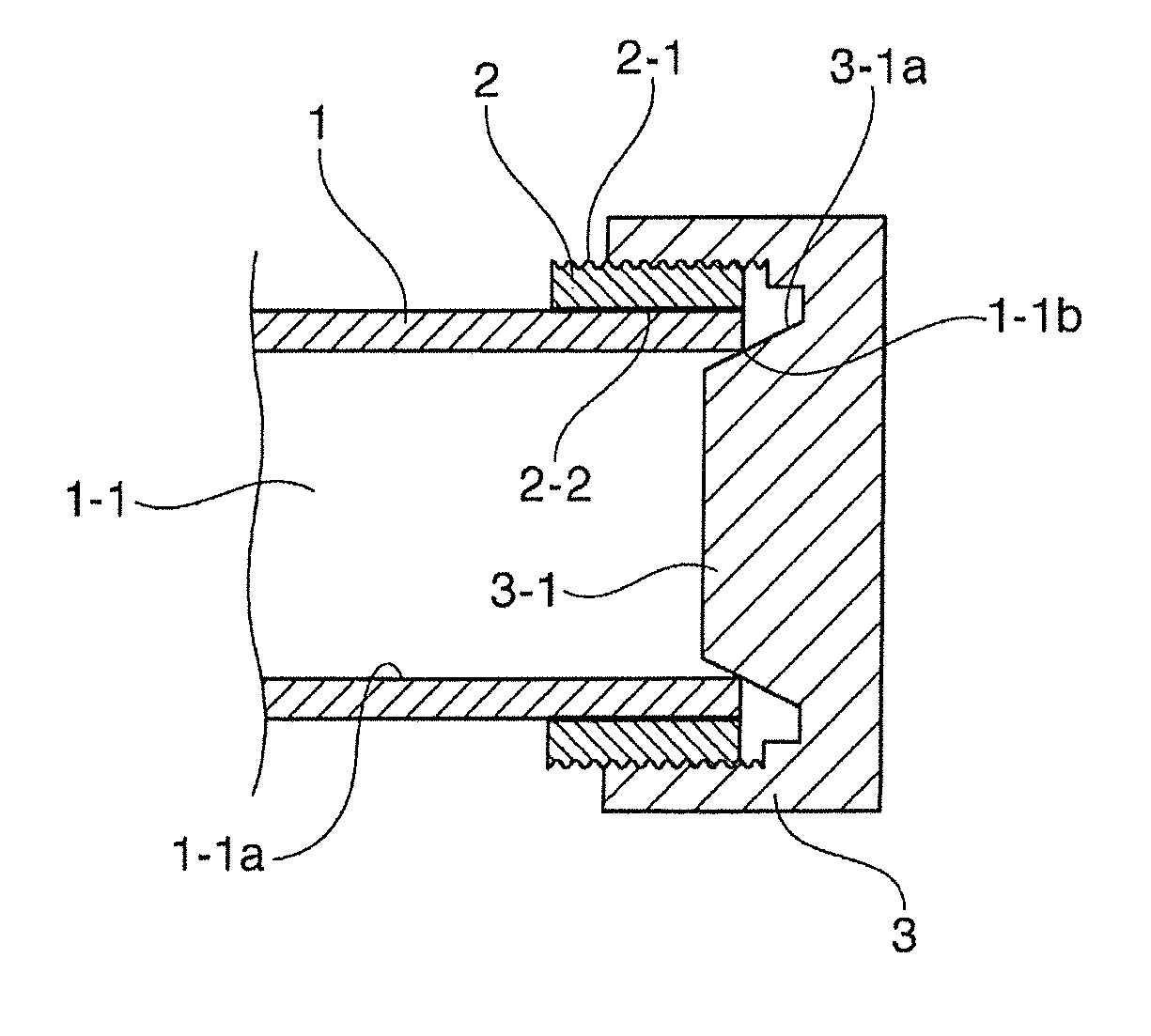
second embodiment
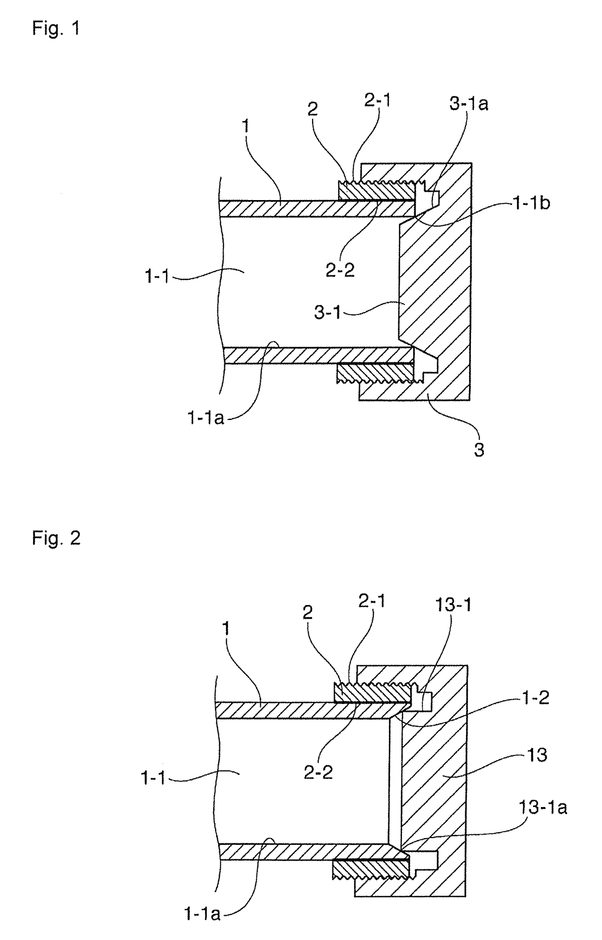
[0025]An end seal structure of a fuel rail for a gasoline direct injection engine in accordance with a second embodiment shown in FIG. 2 employs a sealing mechanism in which an inner surface of an opening at an end of a pipe of a rail body defines a tapered surface with its diameter gradually increased outward, and a front edge of a sealing projection of an end cap having a cap-nut shape brings into pressure contact with the tapered surface and thereby the end of the rail body is sealed. More specifically, as shown in FIG. 2, the tapered surface 1-2 whose diameter gradually increases outward is formed on the inner surface of the opening at the end of the pipe of the rail body 1 having the cylindrical inner circumferential wall surface 1-1a defining the flow passage 1-1 therein, and the collar 2 is joined via the brazed portion 2-2 to the outer circumference of the end of the pipe of the rail body 1 having the tapered surface 1-2 in the same manner as described above, the collar 2 ha...
third embodiment
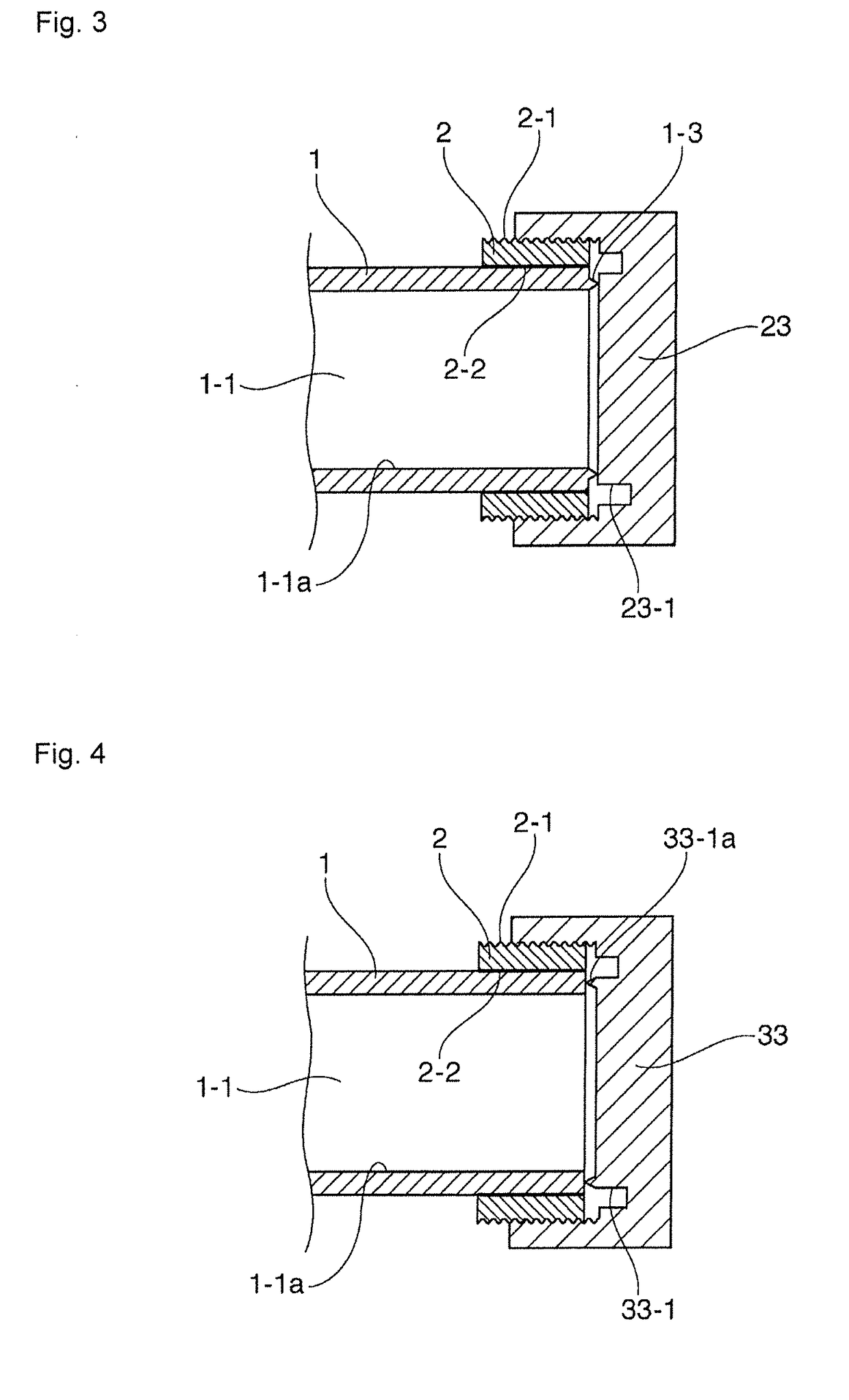
[0027]An end seal structure of a fuel rail for a gasoline direct injection engine in accordance with a third embodiment shown in FIG. 3 employs a sealing mechanism in which an annular projection is formed on an edge face of an opening at the end of a pipe of a rail body, and the annular projection is brought into pressure contact with an end face of the sealing projection of an end cap having a cap-nut shape and thus the end of the rail body is sealed. More specifically, as illustrated in FIG. 3, the annular projection 1-3 is formed on the edge face of the opening at the end of the pipe of the rail body 1 having a cylindrical inner circumferential wall surface 1-1a defining the flow passage 1-1 therein, and in the same manner as described above, the collar 2 is joined via the brazed portion 2-2 to the outer circumference of the pipe end portion of the rail body 1 having the annular projection 1-3, the collar 2 having a short cylindrical body and including an external thread 2-1 the ...
fourth embodiment
[0029]An end seal structure of a fuel rail for a gasoline direct injection engine in accordance with a fourth embodiment shown in FIG. 4 employs a sealing mechanism in which an annular projection is formed on a sealing projection provided on the an end cap having a cap-nut shape, the annular projection is brought into pressure contact with an edge face of an opening at the end of a pipe of a rail body, and thus the end of the rail body is sealed. More specifically, as illustrated in FIG. 4, the collar 2 is joined via the brazed portion 2-2 to an outer circumference of the pipe end portion of the rail body 1 having the cylindrical inner circumferential wall surface 1-1a defining the flow passage 1-1 therein in the same manner as described above, the collar 2 having a short cylindrical body and including the external thread 2-1 on the outer circumferential surface thereof. The cross-sectional structure of the end cap 33 having the cap-nut shape in this embodiment is substantially iden...
PUM
 Abstract
Description
Claims
Application Information