Humidification and air cleaning apparatus

a technology of air cleaning and humidifier, which is applied in lighting and heating apparatus, heating types, separation processes, etc., can solve the problems that typical humidifiers cannot be operated only for air filtration, and its air cleaning function is weak, so as to improve the humidification performance, and reduce noise.

Active Publication Date: 2017-05-04
LG ELECTRONICS INC
View PDF0 Cites 10 Cited by
  • Summary
  • Abstract
  • Description
  • Claims
  • Application Information

AI Technical Summary

Benefits of technology

[0010]The present invention also provides a humidification and air cleaning apparatus which can allow a user to intuitively check with his / her eyes whether humidification is performed.
[0011]The present invention also provides a humidification and air cleaning apparatus for improving a humidification performance by using two types of humidification filters and reducing noise.
[0012]The present invention also provides a humidification and air cleaning apparatus for improving a humidification performance as a discharge humidification medium installed on a discharge flow passage uses a filter with a less water splashing phenomenon and a less pressure loss and a water tank humidification medium installed at a humidification flow passage inlet uses a filter with a high moisture absorption power.

Problems solved by technology

However, since the main function of a typical humidifier is a humidification function, its air cleaning function is weak.
Also, since a typical humidifier has a structure in which the humidification process is performed by adding a filtration function, a typical humidifier cannot be operated only for air filtration.
Accordingly, even in a situation where humidity is high, a typical humidifier inevitably performs humidification even thought a user desires air cleaning.

Method used


Image

  • Humidification and air cleaning apparatus
  • Humidification and air cleaning apparatus
  • Humidification and air cleaning apparatus

Examples


Embodiment Construction

[0043]Advantages and features of the present invention, and implementation methods thereof will be clarified through following embodiments described with reference to the accompanying drawings. The present invention may, however, be embodied in different forms and should not be construed as limited to the embodiments set forth herein. Rather, these embodiments are provided so that this disclosure will be thorough and complete, and will fully convey the scope of the present invention to those skilled in the art. Further, the present invention is only defined by scopes of claims. Like reference numerals refer to like elements throughout.

[0044]Hereinafter, exemplary embodiments of the present invention will be described in detail with reference to the accompanying drawings.

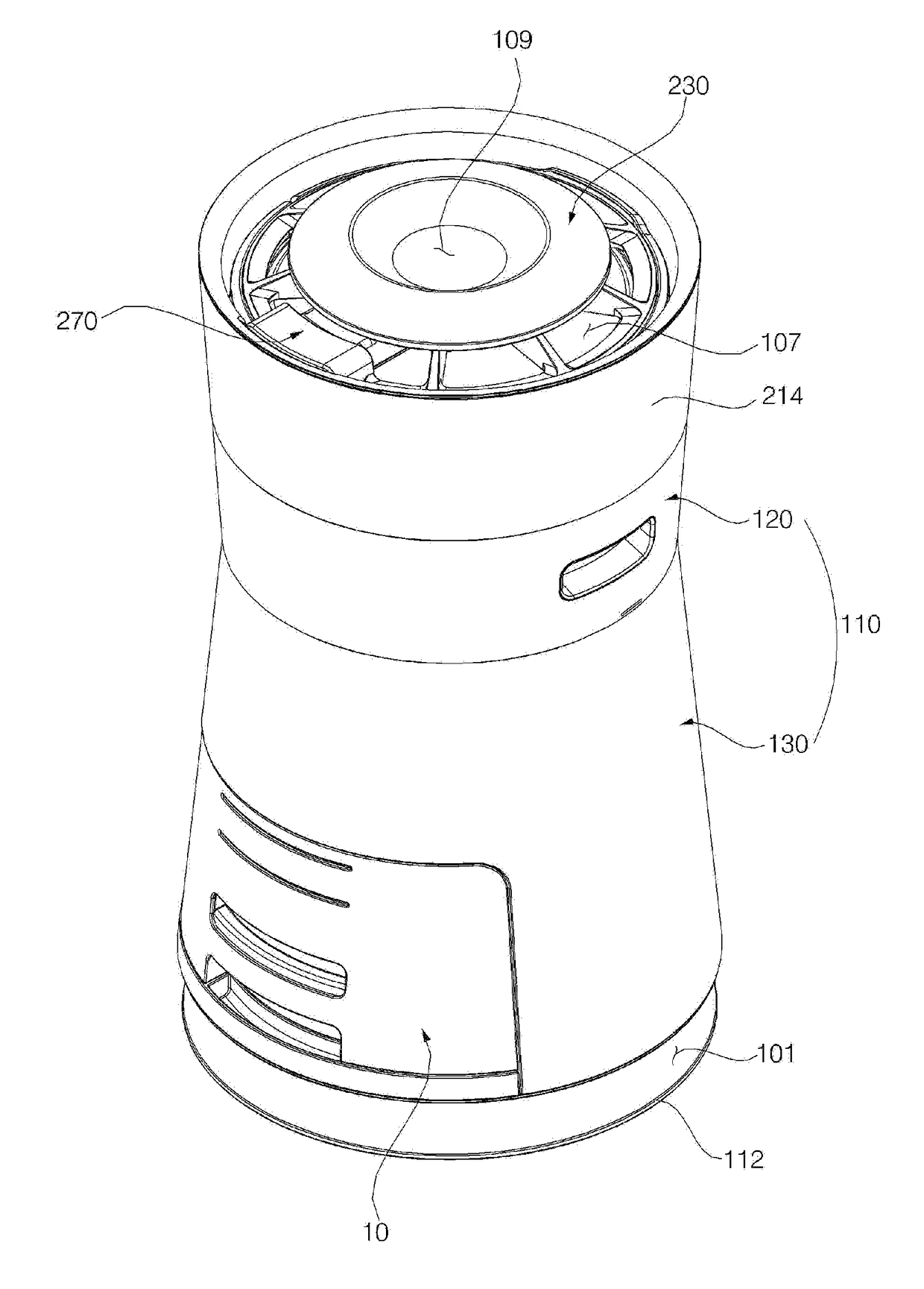
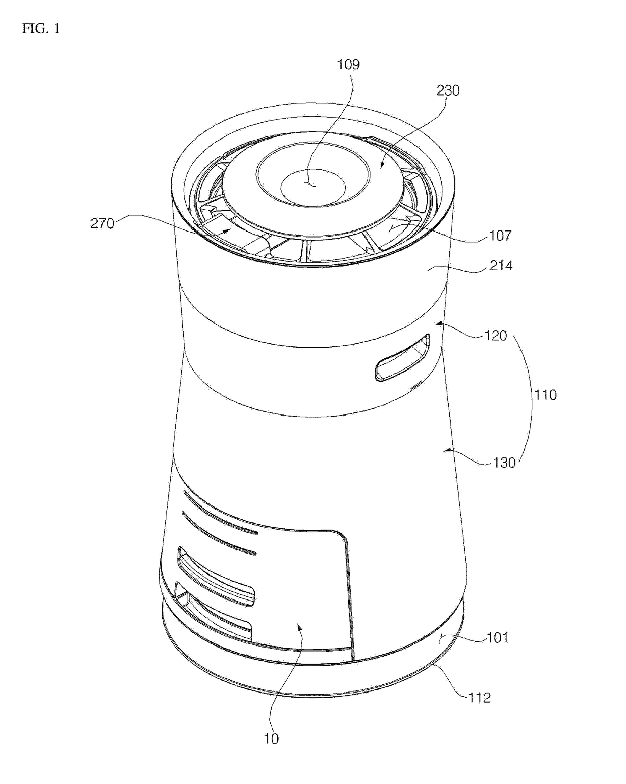
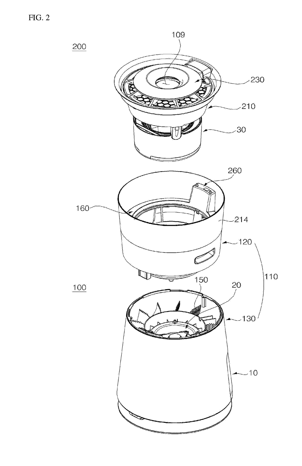
[0045]FIG. 1 is a perspective view illustrating a humidification and air cleaning apparatus according to a first embodiment of the present invention. FIG. 2 is an exploded perspective view of FIG. 1. FIG. 3 is an exp...


PUM

PropertyMeasurementUnit
pressure lossaaaaaaaaaa
structureaaaaaaaaaa
areaaaaaaaaaaa

Abstract

Provided is a humidification and air cleaning apparatus. The humidification and air cleaning apparatus includes an intake flow passage suctioning external air, a discharge flow passage discharging internal air, a blower unit flowing air flowing to the intake flow passage to the discharge flow passage, a discharge humidification medium disposed on the discharge flow passage to additionally humidify flowing air, a water tank humidification medium disposed between the blower unit and the discharge humidification medium to humidify flowing air, and a watering unit spraying water between the water tank humidification medium and the discharge humidification medium.

Description

CROSS-REFERENCE TO RELATED APPLICATIONS[0001]This U.S. non-provisional patent application claims priority under 35 U.S.C. §119 of U.S. Provisional Application No. 62 / 248,463, filed on Oct. 30, 2015, Korean Patent Application No. 10-2015-0156254, filed on Nov. 7, 2015, Korean Patent Application No. 10-2016-0037235, filed on March 28, 2016, U.S. Provisional Application No. 62 / 355,118, filed on Jun. 27, 2016, and Korean Patent Application No. 10-2016-0083081, filed on Jun. 30, 2016, the entire contents of which are hereby incorporated by reference.BACKGROUND OF THE INVENTION[0002]The present invention disclosed herein relates to an apparatus for both humidification and air cleaning.[0003]Air conditioning apparatuses include air conditioners that control the temperature of air, air cleaners that remove foreign substances from air to maintain air cleanliness, humidifiers that increase humidity in the air, and dehumidifiers that reduce humidity in the air.[0004]Typical humidifiers are cla...

Claims


Application Information

Patent Timeline
Patent Type & Authority Applications(United States)
IPC IPC(8): F24F6/04F24F13/28F24F13/20B01D46/10F24F8/117F24F8/125
CPCF24F6/04B01D46/10F24F13/28F24F2006/008B01D2279/50F24F2006/046F24F13/20Y02A50/20F24F8/80F24F8/125F24F3/14F24F8/117B01F23/213B01F23/215
Inventor CHOI, JIEUNKIM, HOJUNGKIM, YONGMINKIM, TAEYOONLEE, KUNYOUNGSON, SANGHYUKLEE, JONGSULEE, KYOUNGHO
Owner LG ELECTRONICS INC
Why Eureka
Try Eureka