Air cleaner

An air purifier and air technology, applied in the direction of air humidification system, air quality improvement, chemical instruments and methods, etc., can solve the problems of low efficiency of air purification, inconvenient replacement, trouble, etc.

Inactive Publication Date: 2003-10-22
N C
View PDF1 Cites 12 Cited by
  • Summary
  • Abstract
  • Description
  • Claims
  • Application Information

AI Technical Summary

Problems solved by technology

But the efficiency of this purifier is also very low
And this purifier uses a charging board to electrically attract dust into the water, but the ai

Method used


Image

  • Air cleaner
  • Air cleaner
  • Air cleaner

Examples


Embodiment 1

[0019] The present invention will be described in detail below with reference to the drawings.

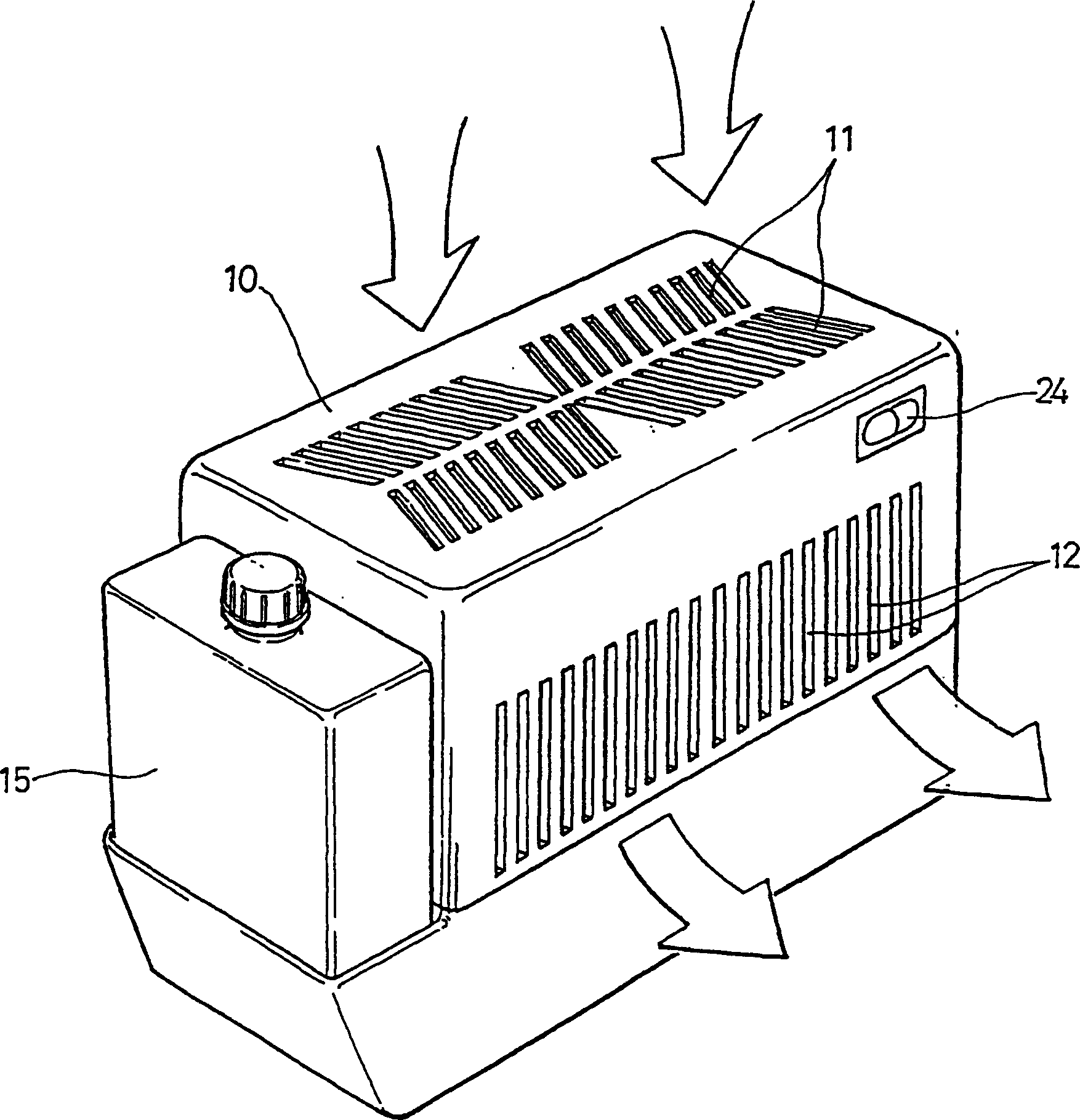
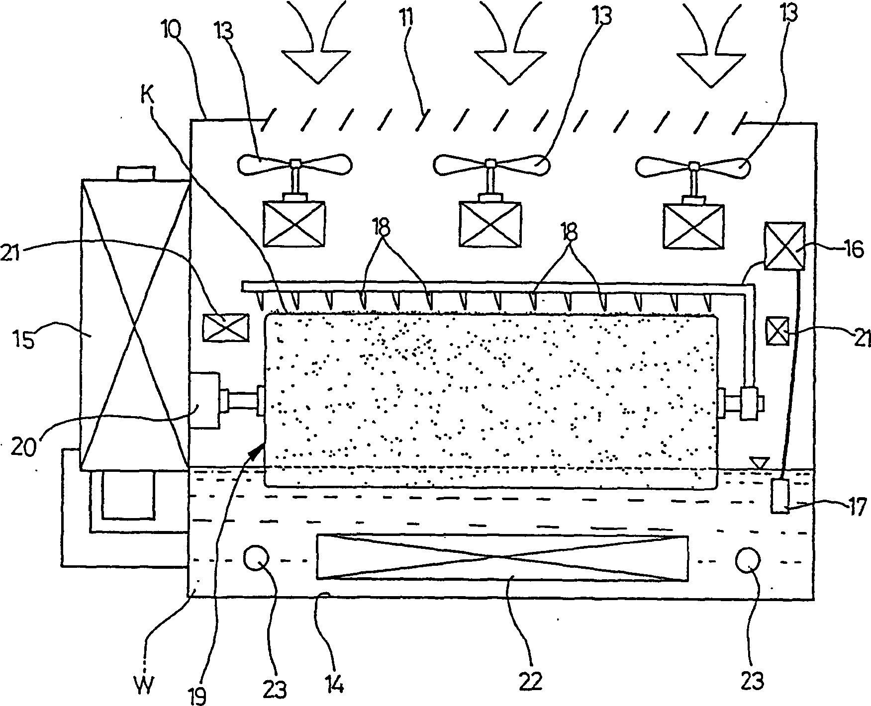
[0020] figure 1 Is a perspective view of the air purifier of the present invention, and figure 2 It is a longitudinal cross-sectional view of the air purifier of Example 1.

[0021] Such as figure 1 with 2 As shown, the air purifier of the present invention includes a main body 10; an exhaust grid 11 arranged on the upper part of the body 10; an exhaust grid 12 installed on the body 10 Side; exhaust fan 13, the exhaust fan is installed in the upper part of the body 10, used to suck in external air through the grid 11. There is a water container under the exhaust fan 13, and the water container is filled with water.

[0022] The water w vapor in the container for humidification must be supplemented with water. Therefore, a supplemental water container 15 is detachably installed on the side of the main body 10, and the main body has a charging circuit 16 for receiving electric energy...

Embodiment 2

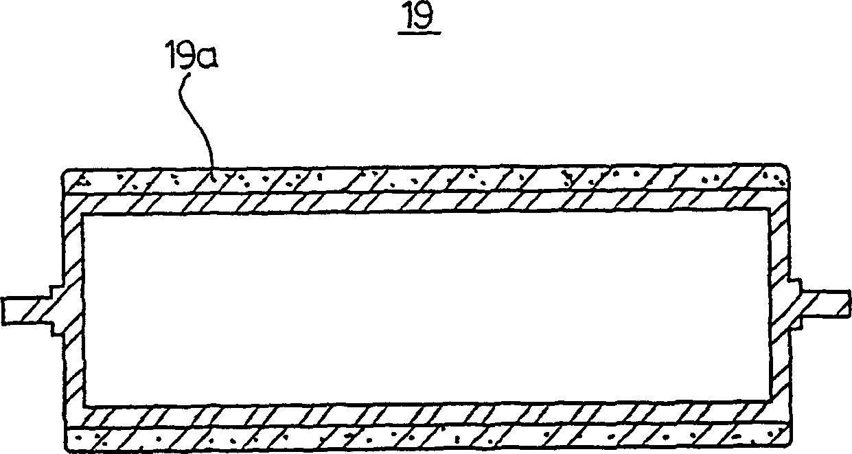
[0043] Figure 4-6 Example 2 of the charging roller of the present invention is shown.

[0044] The charging roller 19 of Embodiment 2 has a plurality of ring-shaped thin fins 19b on its outer circle, and the thin fins are arranged around the roller and have a narrow gap 19c for water filling.

[0045] The charging roller 19 with fins 19b rotates so that its bottom is placed in the water w.

[0046] Therefore, such as Figure 6 As shown, the gap 19c between the fins 19b is filled with water W'in the container, and the water is kept in the gap 19c through the action of surface tension and has a positive charge, which will be contaminated by the vicinity of the needle 18 charged with a negative charge. The substance is sucked into the water in the gap to achieve absorption.

[0047] In addition, the pollutants absorbed in the water W rotate with the roller 19, fall and immerse into the water W, and wash the roller 19 as it continues to rotate.

Embodiment 3

[0049] Figure 7 Example 3 is shown, in which figure 1 with 2The illustrated embodiment has a plurality of charging members 19c installed at the position of the member 19c on the roller 19, and the roller rotates so that the bottom part is immersed in the water W and the upper part is located near the needle 18.

[0050] The energy of the motor 20 or the air flow of the fan 13 is used to rotate the piece 19c having the water W attached to the surface thereof.

[0051] The water W on the surface of the piece 19c has a positive charge, and when it is rotated upward, it will be rotated to reach the vicinity of the needle 18.

[0052] On the other hand, the pollutant K contained in the air around the negatively charged needle 18 will have a negative charge.

[0053] Therefore, the negatively charged pollutants are attracted to the positively charged water attached to the member 19c and absorbed.

[0054] The contaminants absorbed on the upper side of the piece 19c move downward...


PUM


Abstract

The present invention relates to an air cleaner which is very effective in purifying and humidifying air in room and has functions for sterilizing and perfuming air. A main body is provided with an air suction grill and an air discharge grill for a suction fan installed at the inner upper part to suck outer air to blow it over the water in tank to trap and remove pollutants and humidify the cleaned air. The air cleaner also comprises a number of negative charge pins installed above the water in the tank to keep a distance from one another and receive negative electricity to give negative charge to the pollutant, and an electrification roller rotating with the positive charged tank water adhering to its surface in rotation to come close to the negative charged pins to attract and trap negative charged pollutants from the air around the pins into the positive charged water on the roller surface for removal in washing off in the tank.

Description

Technical field [0001] The invention relates to an air purifier for purifying indoor air, in particular to an air purifier with improved air purification and humidification functions and additional air disinfection and fragrance addition functions. Background technique [0002] There are many kinds of indoor air purifiers, and these purifiers are basically divided into two categories, one category is dry cleaners, and the other category is wet cleaners. [0003] Dry air purifiers include negative ion air purifiers, which facilitate the removal of dust and cigarette smoke, but do not have the function of humidifying the air. [0004] Therefore, the air purifier preferably used is a wet type with humidification function. However, the known wet air purifier can only filter out the dust in the air, and the efficiency is too low. [0005] According to the prior art, Korean Patent 10-1999-046485 has a structure of a fan driven by a motor, which facilitates blowing inhaled air through t...

Claims


Application Information

Patent Timeline
IPC IPC(8): B03C3/011B03C3/014B03C3/017B03C3/16B03C3/32B03C3/53F24F6/06F24F8/125F24F8/133F24F8/142
CPCF24F2003/1635F24F3/166B03C3/32F24F2003/1617F24F6/06B03C3/017B03C3/16B03C3/014B03C3/011B03C3/53Y02A50/20F24F8/194F24F8/117F24F8/192F24F8/133F24F8/142F24F8/125
Inventor 朴元金荣洙
Owner N C
Why Eureka
Try Eureka